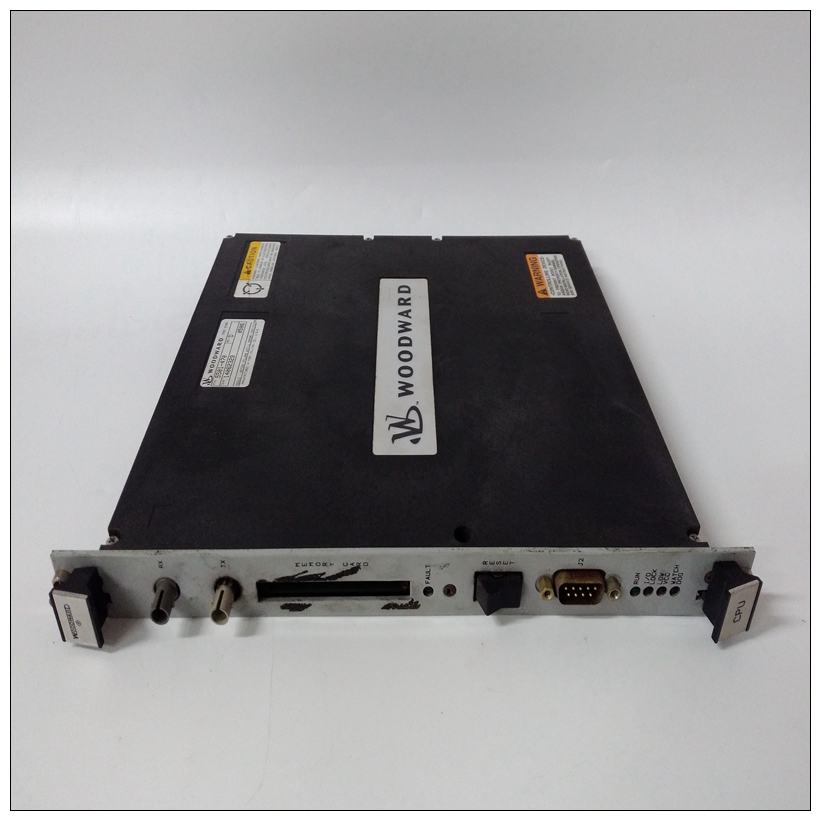
WOODWARD 5501-470伺服调节器,5501-470用户手册
串行通信接口MVME162使用Zilog Z85230串行端口控制器来实现这两个功能串行通信接口。每个接口支持CT、DCD、RTS、,和DTR控制信号以及TxD和RxD发送/接收数据信号和TxC/RxC同步时钟信号。Z85230支持同步(SDLC/HDLC)和异步协议。MVME162硬件支持110B/s至38.4KB/s的异步串行波特率。Z85230在中断确认周期内提供中断向量。


WOODWARD 5501-470伺服调节器根据中断源在Z85230内修改矢量。中断请求级别通过MCchip编程。参见Z85230第1章中列出的数据表和MVME162嵌入式控制器程序员参考指南信息MVME162串行端口1Z85230的端口A连接为EIA-232-D DCE(数据电路终端设备),并路由到标记为串行端口的25针DB25连接器1/MVME162前面板上的控制台。端口A也路由到DB9/RJ11(在MVME712x上)或DB25(在MVME712M上)连接器MVME712系列过渡模块。在那里标识为端口2。虽然两个端口都连接到同一个Z85230端口A,但有它们之间的几个区别:❏ 在MVME162前面板上,端口1可以连接到TxC和RxCDB25连接器上可能存在的时钟信号。这些通过MVME162板上的收割台J11进行连接(见图第2章中的2-3和2-4)。TxC和RxC时钟在端口不可用MVME712系列转换模块上。❏ 在MVME712x转换模块上,端口2可以通过DB9 DTE串行接口或(如果模块如此配备1)通过车载调制解调器及其标准RJ11(电信)插孔。这些连接是通过MVME712x上的跳线头J16和J17制成。❏ 在MVME712M转换模块上,端口2可以配置为通过上的跳线头J16和J17连接DCE或DTE串行端口MVME712M。第2章中的图2-3(第1和2页)和2-4(第1和2页)说明了端口A可用的配置。MVME162串行端口2Z85230的端口B通过串行接口模块配置,该模块是安装在MVME162板上的连接器J10处。四个串行接口模块可用:❏ SIM05和SIM06(分别为EIA-232-D DTE和DCE)
❏ SIM07和SIM08(分别为EIA-530 DTE和DCE)
Serial Communications Interface
The MVME162 uses a Zilog Z85230 serial port controller to implement the two
serial communications interfaces. Each interface supports CTS, DCD, RTS,
and DTR control signals as well as the TxD and RxD transmit/receive data
signals, and TxC/RxC synchronous clock signals. The Z85230 supports
synchronous (SDLC/HDLC) and asynchronous protocols. The MVME162
hardware supports asynchronous serial baud rates of 110B/s to 38.4KB/s.The Z85230 supplies an interrupt vector during interrupt acknowledge cycles.
The vector is modified within the Z85230 according to the interrupt source.
Interrupt request levels are programmed via the MCchip. Refer to the Z85230
data sheet listed in Chapter 1 and to the MCchip Programming Model in the
MVME162 Embedded Controller Programmer’s Reference Guide for further
information.
MVME162 Serial Port 1
Port A of the Z85230 is interfaced as EIA-232-D DCE (data circuit-terminating
equipment) and is routed to the 25-pin DB25 connector marked SERIAL PORT
1/CONSOLE on the MVME162 front panel. Port A is also routed to a DB9/RJ11
(on the MVME712x) or DB25 (on the MVME712M) connector on the
MVME712 series transition module. It is identified there as Port 2.
Although both ports are connected to the same Z85230 Port A, there are
several differences between them:
❏ On the MVME162 front panel, Port 1 can be connected to the TxC and RxC
clock signals which may be present on the DB25 connector. These
connections are made via header J11 on the MVME162 board (see Figures
2-3 and 2-4 in Chapter 2). The TxC and RxC clocks are not available at Port
2 on the MVME712 series transition modules.
❏ On MVME712x transition modules, Port 2 can be routed either through a
DB9 DTE serial interface or (if the module is so equipped1) through the
onboard modem and its standard RJ11 (Telco) jack. These connections are
made via jumper headers J16 and J17 on the MVME712x.
❏ On MVME712M transition modules, Port 2 can be configured as either a
DCE or a DTE serial port via jumper headers J16 and J17 on the
MVME712M.
Figures 2-3 (sheets 1 and 2) and 2-4 (sheets 1 and 2) in Chapter 2 illustrate the
configurations available for Port A.
MVME162 Serial Port 2
Port B of the Z85230 is configured via a serial interface module which is
installed at connector J10 on the MVME162 board. Four serial interface
modules are available:
❏ SIM05 and SIM06 (EIA-232-D DTE and DCE respectively)
❏ SIM07 and SIM08 (EIA-530 DTE and DCE respectively)


