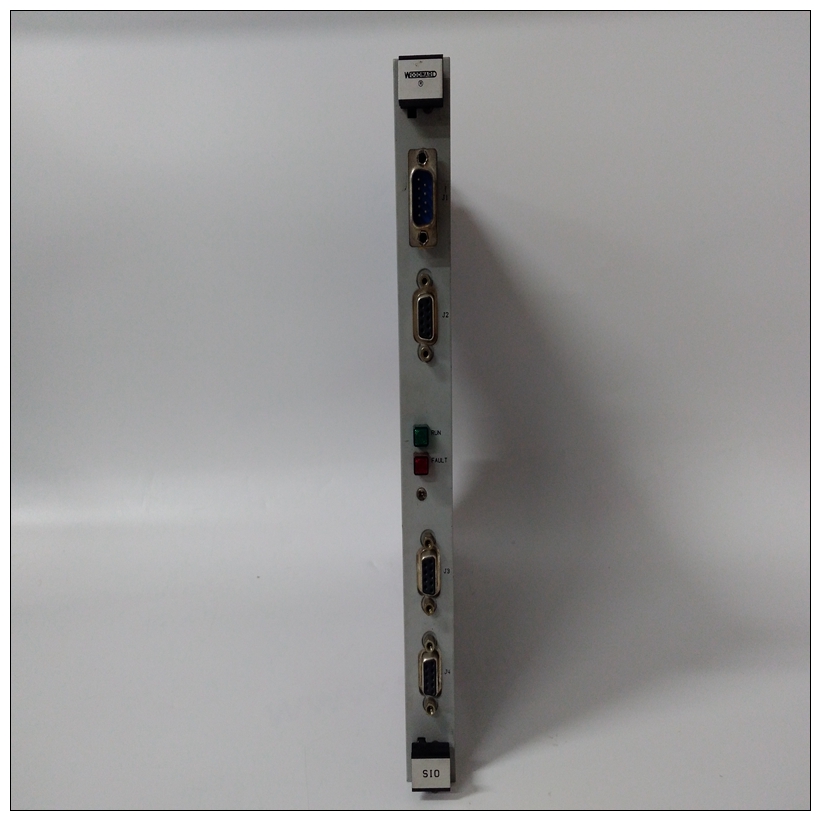
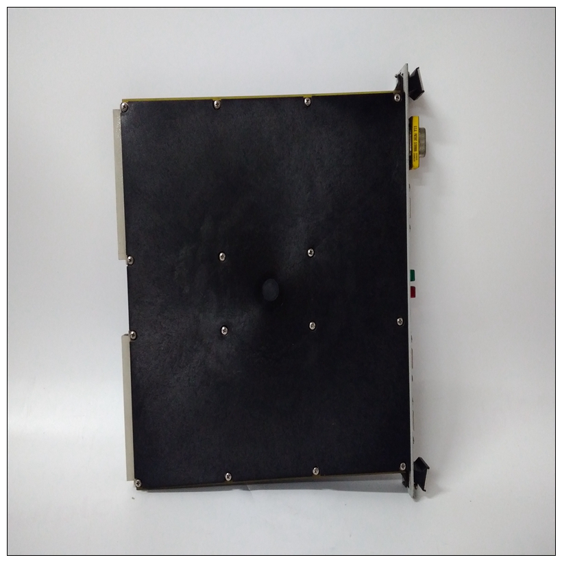
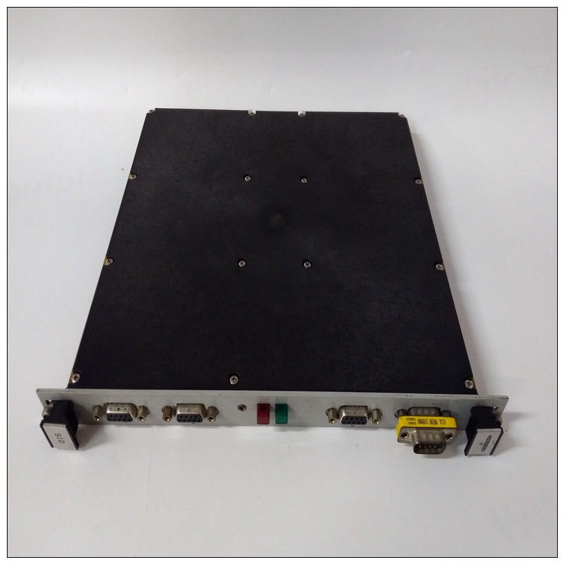
WOODWARD 5501-471控制调节器,5501-471使用教程
端口B(通过J10处的模块)连接到标有MVME162前面板上的串行端口2。端口B也路由到DB9(onMVME712x)或MVME712M上的DB25连接器串联转换模块。在那里标识为端口4。虽然两个端口都连接到同一个Z85230端口B,但有几个要记住的注意事项:❏ 在MVME162前面板上,端口2可以连接到TxC和RxCDB25连接器上可能存在的时钟信号。


WOODWARD 5501-471控制调节器这些通过MVME162板上的收割台J12进行连接(见图第2章中的2-3、2-4和2-5)。TxC和RxC时钟线也是MVME712M过渡模块的端口4可用。❏ 在MVME712x转换模块上,端口4作为EIA-232-D硬接线DB9 DTE串行端口。使用“零调制解调器”电缆作为DCE是必要的港口城市❏ 在MVME712M转换模块上,端口4可以配置为DTE或DCE EIA-232-D串行端口通过上的跳线头J19和J18MVME712M。端口4也可以连接到TxC和RxC时钟DB25连接器上可能存在的信号。这些连接通过MVME712M上的收割台J15制作(见图2-3,第3-6页第2章)。❏ 当端口B配置为EIA-530接口时,EIA-530数据传输通常通过MVME162前面板上的串行端口2发生。这个MVME712系列转换模块应与MVME162。虽然P2处存在信号(见图2-5),但EIA-530标准要求使用DB25连接器和平衡(非单端)线路;P2适配器和MVME712系列转换不支持这些功能模块。希望在P2使用EIA-530信号的系统集成商必须提供适当的连接。第2章中的图2-3(第3-6页)、图2-4(第3-4页)和图2-5说明端口B的工厂配置。请注意不建议将图2-3第5页和第6页中所示的配置用于由于时钟方向不正确而导致的同步应用。不要将串行数据设备连接到上的等效端口MVME712系列转换模块和MVME162同时安装前面板。这可能导致冲突数据的同时传输。不要将外围设备连接到端口1、端口3或MVME712系列转换上的Centronics打印机端口单元在EIA-232-D情况下,这些端口均未连接到任何MVME162电路。在EIA-530案例中,试图使用这些端口会产生某些连接,可能会损坏MVME162或外围设备。
Port B is routed (via the module at J10) to the 25-pin DB25 connector marked
SERIAL PORT 2 on the MVME162 front panel. Port B is also routed to a DB9 (on
the MVME712x) or DB25 (on the MVME712M) connector on the MVME712
series transition module. It is identified there as Port 4.
Although both ports are connected to the same Z85230 Port B, there are several
considerations to keep in mind:
❏ On the MVME162 front panel, Port 2 can be connected to the TxC and RxC
clock signals which may be present on the DB25 connector. These
connections are made via header J12 on the MVME162 board (see Figures
2-3, 2-4, and 2-5 in Chapter 2). The TxC and RxC clock lines are also
available at Port 4 on MVME712M transition modules.
❏ On MVME712x transition modules, Port 4 is hard-wired as an EIA-232-D
DB9 DTE serial port. A ‘‘null modem’’ cable is necessary to use it as a DCE
port.
❏ On MVME712M transition modules, Port 4 can be configured as either a
DTE or DCE EIA-232-D serial port via jumper headers J19 and J18 on the
MVME712M. Port 4 can also be connected to the TxC and RxC clock
signals which may be present on the DB25 connector. These connections
are made via header J15 on the MVME712M (see Figure 2-3, sheets 3-6 in
Chapter 2).
❏ When Port B is configured as an EIA-530 interface, EIA-530 data transfers
normally occur through serial port 2 on the MVME162 front panel. The
MVME712 series transition module should be disconnected from the
MVME162.
Although the signals are present at P2 (see Figure 2-5), the EIA-530
standard calls for a DB25 connector and balanced (not single-ended) lines;
these are not supported by the P2 adapter and MVME712 series transition
modules. System integrators who wish to use the EIA-530 signals at P2
must provide the appropriate connections.
Figure 2-3 (sheets 3-6), Figure 2-4 (sheets 3-4), and Figure 2-5 in Chapter 2
illustrate the factory configurations available for Port B. Note that the port
configurations shown in Figure 2-3, sheets 5 and 6 are not recommended for
synchronous applications because of the incorrect clock direction.Do not connect serial data devices to the equivalent ports on
the MVME712 series transition module and the MVME162
front panel at the same time. This could result in simultaneous transmission of conflicting data.
Do not connect peripheral devices to Port 1, Port 3, or the
Centronics printer port on the MVME712 series transition
module. In the EIA-232-D case, none of these ports are connected to any MVME162 circuits. In the EIA-530 case,
attempting to use these ports would produce certain connections with the potential to damage the MVME162 or the
peripherals.


