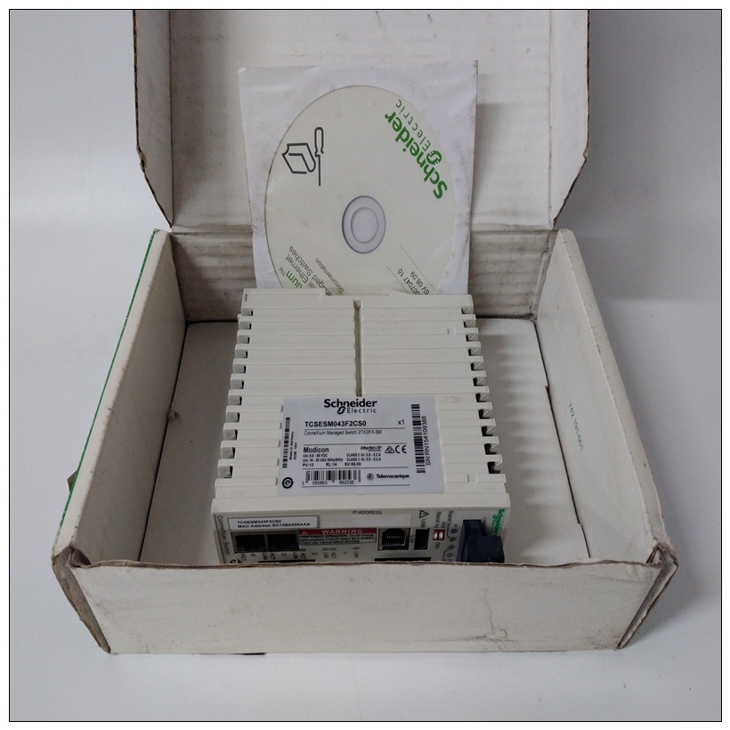
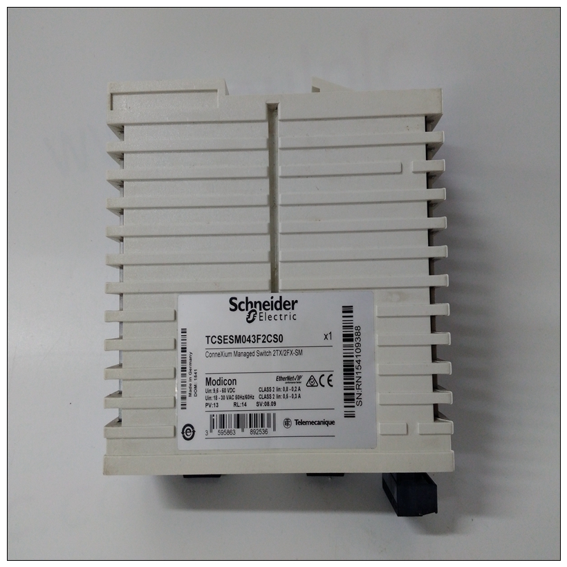
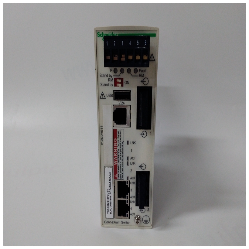
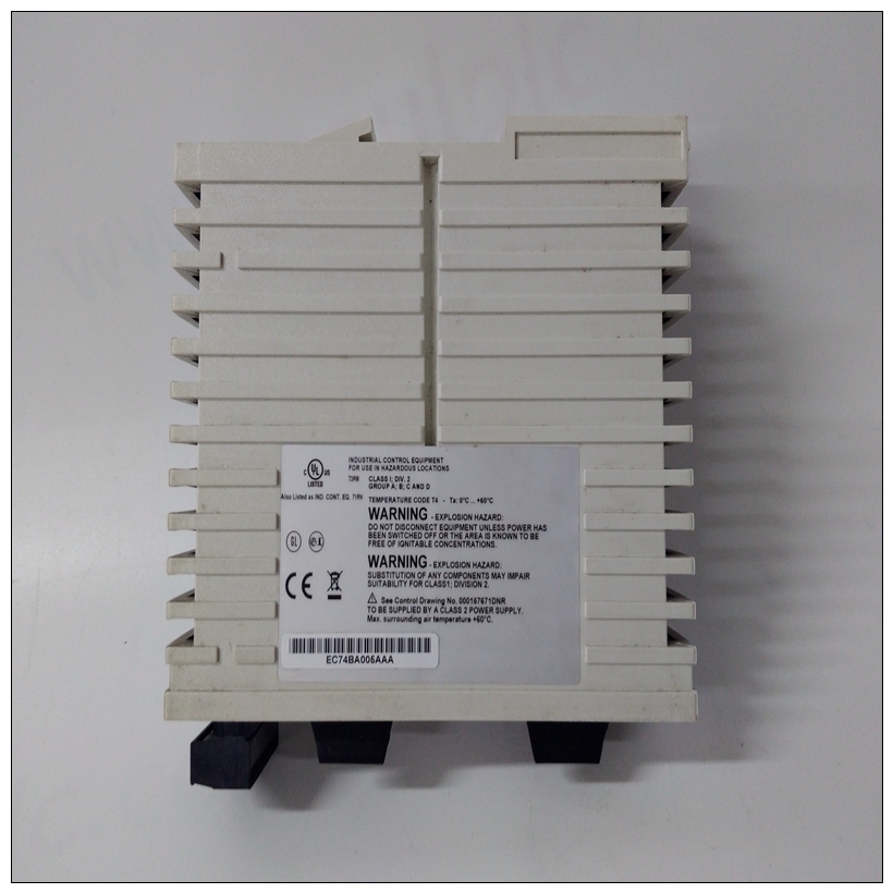
TCSESM043F2CS0以太网交换机,SCHNEIDER配置说明
写入VMEchip2中的LCSR必须为32位。LCSR8位或16位的写入以TEA信号终止。写入GCSR可以是8、16或32位。读取LCSR和GCSR可以是8位、16位或32位。应使用字节读取来读取中断向量。4.该区域不返回确认信号。如果当地总线计时器启用,访问超时,并通过以下方式终止茶的信号。5、尺寸为近似值。6.82596CA的端口命令必须写入两个16位写:第一个上单词,第二个下单词。


TCSESM043F2CS0以太网交换机7.参考MCchip中的闪存和EPROM接口部分第3章中的说明。详细的输入/输出内存映射表3-3至3-12提供了VMEchip2的详细内存映射MCchip,Zilog Z85230串行通信控制器,Intel 82596CALAN控制器、NCR 53C710 SCSI控制器、IPIC芯片和MK48T08 BBRAM/TOD时钟。划分MK48T08 BBRAM(也称为非易失性RAM或NVRAM)分为六个区域,如表3-10所示。前五个领域的定义如下:软件,而第六个区域,即一天中的时间(TOD)时钟,由芯片硬件。第一个区域是为用户数据保留的。使用第二个区域摩托罗拉网络软件。第三个区域由操作人员使用系统第四个区域由MVME162板调试器使用(MVME162Bug)。第五个区域是配置,详见表3-11地区第六个区域,即TOD时钟,详见表3-12,由芯片硬件。配置字节的数据结构从$FFFC1EF8开始,如下所示跟随。字段定义如下:1、本结构的修订或版本保留四个字节。这
版本以ASCII格式存储,前两个字节为主要字节版本号,最后两个字节是次要版本号。例如,如果此结构的版本为1.0,则此字段包含:01002.ASCII中为板的序列号保留了12个字节
总体安排例如,该字段可以包含:0000004704763.ASCII格式的板ID保留了16个字节。例如
对于带有MC68040、SCSI、以太网、4MB DRAM和512KB SRAM,此字段包含:MVME162-23(10个字符后接6个空格。)4.16个字节用于印刷线路组件(PWA)编号以ASCII格式分配给该电路板。这包括01-W前缀。这如果一个集合需要多个板,则用于主逻辑板。集合中的其他板由该集合的结构定义。对于例如,对于带有MC68040、SCSI、以太网、4MB的MVME162板
DRAM和512KB SRAM,在版本A中,PWA字段包含:01-W3814B01A(12个字符后接四个空格。)
Writes to the LCSR in the VMEchip2 must be 32 bits. LCSR
writes of 8 or 16 bits terminate with a TEA signal. Writes to the
GCSR may be 8, 16 or 32 bits. Reads to the LCSR and GCSR
may be 8, 16 or 32 bits. Byte reads should be used to read the
interrupt vector.
4. This area does not return an acknowledge signal. If the local
bus timer is enabled, the access times out and is terminated by
a TEA signal.
5. Size is approximate.
6. Port commands to the 82596CA must be written as two 16-bit
writes: upper word first and lower word second.
7. Refer to the Flash and EPROM Interface section in the MCchip
description in Chapter 3.
Detailed I/O Memory Maps
Tables 3-3 through 3-12 provide detailed memory maps for the VMEchip2, the
MCchip, the Zilog Z85230 serial communications controller, the Intel 82596CA
LAN controller, the NCR 53C710 SCSI controller, the IPIC chip, and the
MK48T08 BBRAM/TOD Clock.The MK48T08 BBRAM (also called Non-Volatile RAM or NVRAM) is divided
into six areas as shown in Table 3-10. The first five areas are defined by
software, while the sixth area, the time-of-day (TOD) clock, is defined by the
chip hardware. The first area is reserved for user data. The second area is used
by Motorola networking software. The third area is used by the operating
system. The fourth area is used by the MVME162 board debugger
(MVME162Bug). The fifth area, detailed in Table 3-11, is the configuration
area. The sixth area, the TOD clock, detailed in Table 3-12, is defined by the
chip hardware.
The data structure of the configuration bytes starts at $FFFC1EF8 and is as
follows.The fields are defined as follows:
1. Four bytes are reserved for the revision or version of this structure. This
revision is stored in ASCII format, with the first two bytes being the major
version numbers and the last two bytes being the minor version numbers.
For example, if the version of this structure is 1.0, this field contains:
0100
2. Twelve bytes are reserved for the serial number of the board in ASCII
format. For example, this field could contain:
000000470476
3. Sixteen bytes are reserved for the board ID in ASCII format. For example,
for an MVME162 board with MC68040, SCSI, Ethernet, 4MB DRAM, and
512KB SRAM, this field contains:
MVME162-23 (The 10 characters are followed by six blanks.)
4. Sixteen bytes are reserved for the printed wiring assembly (PWA) number
assigned to this board in ASCII format. This includes the 01-W prefix. This
is for the main logic board if more than one board is required for a set.
Additional boards in a set are defined by a structure for that set. For
example, for an MVME162 board with MC68040, SCSI, Ethernet, 4MB
DRAM, and 512KB SRAM, at revision A, the PWA field contains:
01-W3814B01A (The 12 characters are followed by four blanks.)


