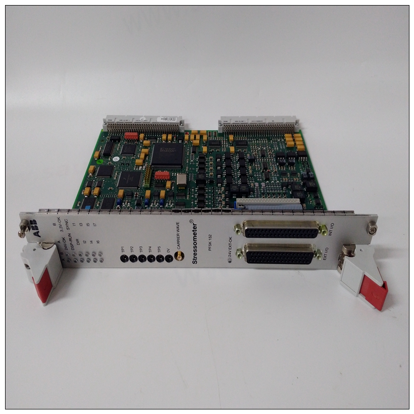
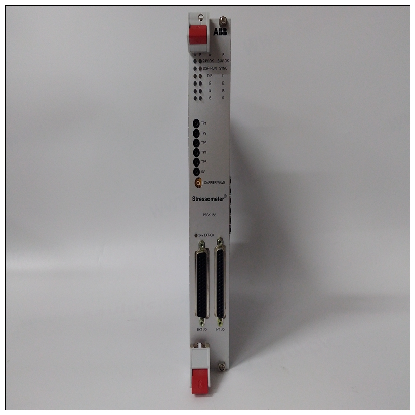
PFSK152 3BSE018877R2 3BSC980006R361模块卡件
通常需要通过将CT连接到RTS或一些+12伏电源,如图A-1所示的电阻器。
电流互感器也经常跨接至MC1488门,该门具有输入接地(为此提供栅极)。
许多系统中使用的另一个信号是DCD。最初的目的该信号的目的是通知系统来自正在接收远程调制解调器。该信号经常使用由软件显示信息,如承运人不在场帮助用户诊断通信故障。显然,如果系统正确设计为使用该信号,且未连接对于调制解调器,信号必须由上拉电阻器或闸门如上所述(见图A-1)。许多调制解调器期望DTR高信号并发出DSR响应。


PFSK152 3BSE018877R2 3BSC980006R361模块卡件软件使用这些信号来帮助提示操作员关于可能的故障原因。有时使用DTR信号断开电话电路以准备另一个自动呼叫这些信号是与所有人通信所必需的可能的调制解调器(见图A-1)。示例配置图A-1是一个良好的中间道路配置,几乎始终有效。如果未从接收到CT和DCD信号调制解调器,跳线可以移动以人为提供需要的信号。图A-2显示了连接EIA-232-D连接器以启用一种仅用三条线连接到基本终端的计算机。这是可行的,因为大多数终端都有DTR和RTS信号开启,可用于拉起CT、DCD和DSR信号。可以使用其中两个背靠背接线的连接器。在这个然而,在实现过程中,诊断消息可能会否则不会生成,因为所有握手都是绕过。此外,TX和RX线路可能必须交叉因为来自终端的发送是传出的,但调制解调器上的发送线路是输入信号。另一个需要考虑的问题是接地引脚的使用。有两个标有GND的引脚。针脚7是信号接地,必须连接到远程设备以完成电路。针脚1是底盘接地,但必须小心使用。机箱是通过中的绿色导线连接到电源接地电源线和必须连接到机箱才能进入符合电气规范。
usually necessary to make CTS high by connecting it to RTS or to
some source of +12 volts such as the resistors shown in Figure A-1.
CTS is also frequently jumpered to an MC1488 gate which has its
inputs grounded (the gate is provided for this purpose).
Another signal used in many systems is DCD. The original purpose
of this signal was to inform the system that the carrier tone from the
distant modem was being received. This signal is frequently used
by the software to display a message such as CARRIER NOT PRESENT to
help the user diagnose failure to communicate. Obviously, if the
system is designed properly to use this signal and is not connected
to a modem, the signal must be provided by a pullup resistor or
gate as described above (see Figure A-1).
Many modems expect a DTR high signal and issue a DSR response.
These signals are used by software to help prompt the operator
about possible causes of trouble. The DTR signal is sometimes used
to disconnect the phone circuit in preparation for another automatic
call. These signals are necessary in order to communicate with all
possible modems (see Figure A-1).
Sample Configurations
Figure A-1 is a good middle-of-the-road configuration that almost
always works. If the CTS and DCD signals are not received from the
modem, the jumpers can be moved to artificially provide the
needed signal.Figure A-2 shows a way of wiring an EIA-232-D connector to enable
a computer to connect to a basic terminal with only three lines. This
is feasible because most terminals have DTR and RTS signals that
are ON, and which can be used to pull up the CTS, DCD, and DSR
signals.
Two of these connectors wired back-to-back can be used. In this
implementation, however, diagnostic messages that might
otherwise be generated do not occur because all the handshaking is
bypassed. In addition, the TX and RX lines may have to be crossed
since TX from a terminal is outgoing but the TX line on a modem is
an incoming signal.Another subject to consider is the use of ground pins. There are two
pins labeled GND. Pin 7 is the SIGNAL GROUND and must be
connected to the distant device to complete the circuit. Pin 1 is the
CHASSIS GROUND, but it must be used with care. The chassis is
connected to the power ground through the green wire in the
power cord and must be connected to the chassis to be in
compliance with the electrical code.


