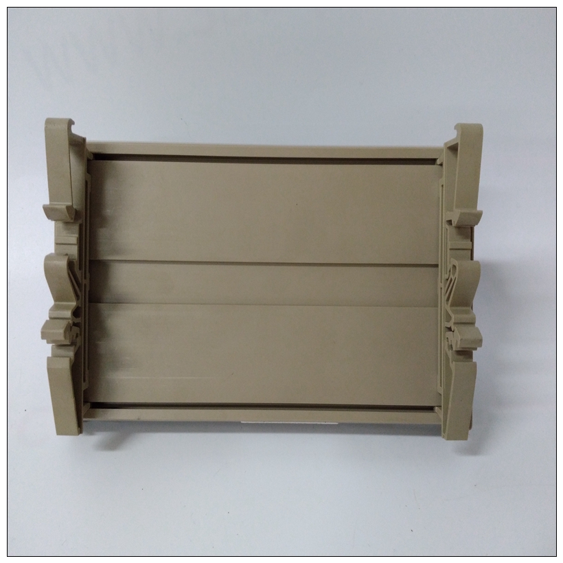
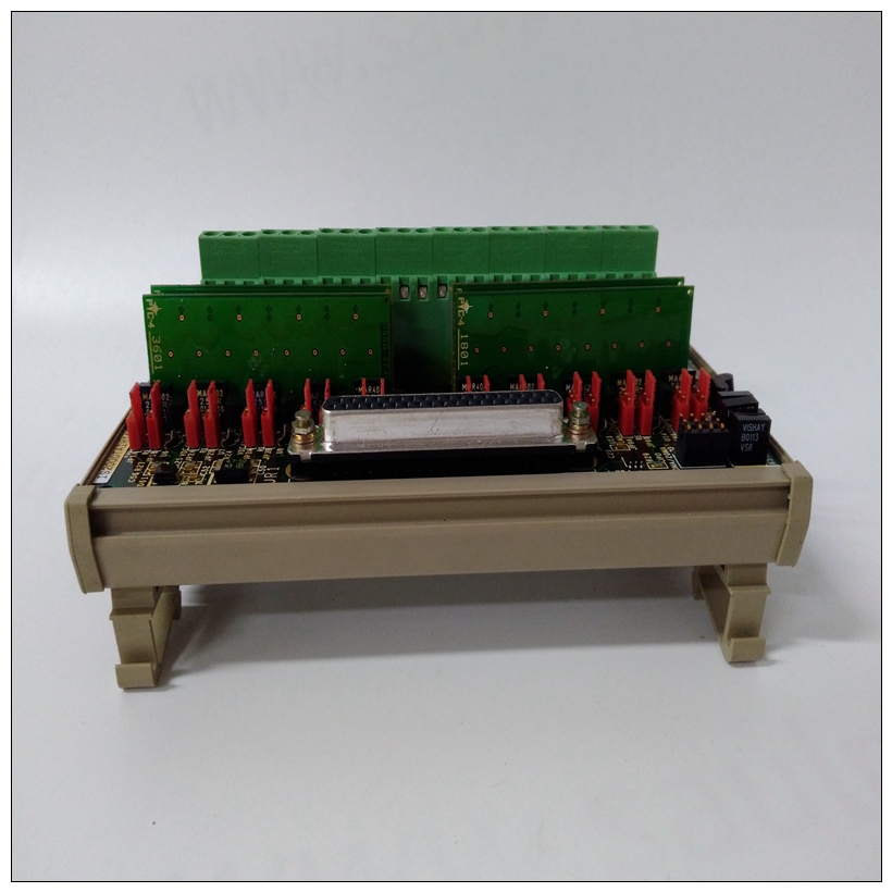
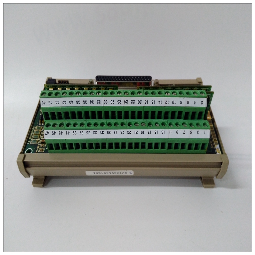
IS200DTAIH1ABB IS210DTAOH1AA燃机卡件,GE实验数据
EEPROM通电/断电注意事项MVME147不提供对意外写入的保护可能在通电或断电时发生的EEPROM。大多数设备提供一定程度的内部保护。获得带有附加“软件”的“绝对保护”装置建议使用“保护”。中断处理程序MC68030可能会被多个电源中断。所有中断源是软件启用/禁用的。有些人有软件可编程电平和所有中断源提供一个矢量在中断确认周期内。PCC芯片解码MC68030地址总线和功能确定中断周期何时进行的代码。


IS200DTAIH1ABB IS210DTAOH1AA燃机卡件当PCC在其水平上检测中断确认周期中断,它传递状态/ID向量。否则向VMEchip生成中断确认输出信号。
当VMEchip在信号中检测到中断确认时从PCC,它在该级别中断,它通过一个状态/ID向量。否则,它将请求VMEbus的主控权(如果没有主控权),并驱动VMEbus信号启动中断确认周期的线路。打断从机返回状态/ID向量。在一个级别内,来自PCC的中断具有最高的VMEchip和VMEbus中断后的优先级最低优先级。前面板开关和指示灯MVME147的前面板上有两个开关。这个开关复位并中止。重置开关重置所有车载设备并驱动系统重置*如果MVME147是系统控制器。复位开关可能是被软件禁用。请参阅复位和中止开关本章第节。启用时,中止开关生成7级中断。它是通常用于中止程序执行并返回到调试器。中止开关可以通过软件禁用。提到
本章中的重置和中止开关部分。
MVME147的前面板上有四个LED指示灯。
指示器为RUN、STATUS、FAIL和SCON。
❏ 当MC68030地址选通(AS*)引脚低时,RUN点亮。
❏ 当MC68030状态*引脚低时,状态点亮。
❏ 当在中设置Board FAIL(BRDFAIL)位时,FAIL点亮
VMEchip或PCC中出现看门狗超时时。
❏ 当MVME147是VMEbus系统时,SCON点亮
控制器(由跳线J3选择)。
EEPROM Power-Up/Power-Down Considerations
The MVME147 provides no protection against inadvertent writes to
EEPROM that might happen at power-up or power-down time.
Most devices provide some level of internal protection. To gain
“absolute protection” devices with additional “software
protection” are recommended.
Interrupt Handler
The MC68030 may be interrupted by many sources. All interrupt
sources are software enabled/disabled. Some have software
programmable levels and all interrupt sources supply a vector
during an interrupt acknowledge cycle.
The PCC chip decodes the MC68030 address bus and function
codes to determine when an interrupt cycle is in progress. When the
PCC detects an interrupt acknowledge cycle at the level it is
interrupting on, it passes a status/ID vector. Otherwise, it
generates an interrupt acknowledge out signal to the VMEchip.
When the VMEchip detects an interrupt acknowledge in signal
from the PCC and it is interrupting at that level, it passes a
status/ID vector. Otherwise, it requests mastership of the VMEbus
(if it does not have mastership), and it drives the VMEbus signal
lines to initiate an interrupt acknowledge cycle. The interrupting
slave returns a status/ID vector.
Within a level, the interrupts from the PCC have the highest
priority followed by the VMEchip and the VMEbus interrupts have
the lowest priority. Front Panel Switches and Indicators
There are two switches on the front panel of the MVME147. The
switches are RESET and ABORT.
The RESET switch resets all onboard devices and drives SYSRESET*
if the MVME147 is the system controller. The RESET switch may be
disabled by software. Refer to the RESET and ABORT Switches
section in this chapter.
The ABORT switch generates a Level 7 interrupt when enabled. It is
normally used to abort program execution and return to the
debugger. The ABORT switch may be disabled by software. Refer to
the RESET and ABORT Switches section in this chapter.
There are four LED indicators on the front panel of the MVME147.
The indicators are RUN, STATUS, FAIL, and SCON.
❏ RUN is lit when the MC68030 Address Strobe (AS*) pin is low.
❏ STATUS is lit when the MC68030 STATUS* pin is low.
❏ FAIL is lit when the Board Fail (BRDFAIL) bit is set in the
VMEchip or when watchdog time-out occurs in the PCC.
❏ SCON is lit when the MVME147 is the VMEbus system
controller (selected by jumper J3).


