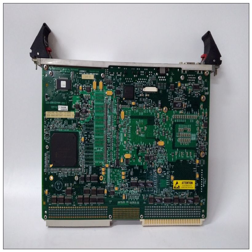
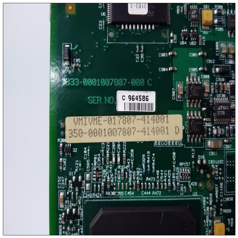
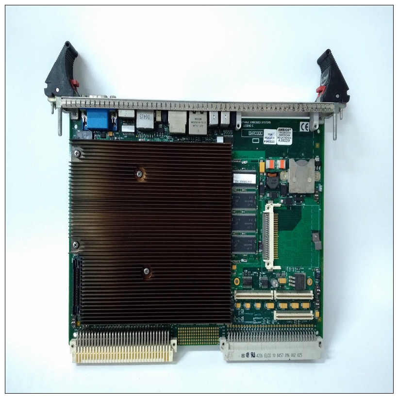
VMIVME-7807-411001 350-0001007807-411001 B燃机模块
该位选择打印机选通的自动或手动模式。当该位较低时,打印机选通由写入生成打印机数据寄存器(自动模式)。当该位较高时打印机选通不是通过写入打印机数据生成的寄存器(手动模式)。该位通过重置清除。位1该位控制自动模式下的打印机选通定时。当该位较低时,自动模式下的选通时间为2微秒。


VMIVME-7807-411001 350-0001007807-411001 B燃机模块当该位高时,自动模式中的选通时间模式为8微秒。选通时间也是时间延迟从写入打印机数据寄存器到打印机选通。该位通过重置清除。位2该位控制手动模式下的打印机选通。在手动模式下,软件必须控制定时。当这个位低,打印机选通未激活。当此位为高,打印机选通被激活。该位通过重置清除。位3该位控制输入主信号。当该位较低时输入主信号未激活。当该位较高时输入主信号激活。软件必须控制打印机输入主信号的定时。该位被清除重置。位设置和清除指令不应用于此控制寄存器。因为中断被将1写入状态位,状态位为1至指示挂起的中断,读-修改-写序列可能清除挂起的中断。这些位对DMA控制器的中断级别进行编程生成。级别0不生成中断。这些位是通过重置清除。位3当该位为高位时,中断被启用。中断是此位低时禁用。该位通过重置清除。位7当该位为高位时,DMA中断在以位0-2编程的电平。该位是边缘敏感的设置在中断启用和DMA完成的前沿(inDMA控制和状态寄存器)。当1时,该位被清除或当中断被禁用时写入。清除后,它保持清除状态,直到中断启用的下一个前沿DMA完成。该位通过重置清除。
This bit selects the auto or manual mode for the printer strobe.
When this bit is low, the printer strobe is generated by a write to
the printer data register (auto mode). When this bit is high, the
printer strobe is not generated by a write to the printer data
register (manual mode). This bit is cleared by reset.
Bit 1 This bit controls the printer strobe timing in the auto mode.
When this bit is low, the strobe time in the auto mode is 2
microseconds. When this bit is high, the strobe time in the auto
mode is 8 microseconds. The strobe time is also the time delay
from the write to the printer data register to the assertion of the
printer strobe. This bit is cleared by reset.
Bit 2 This bit controls the printer strobe in the manual mode. In the
manual mode, the software must control the timing. When this
bit is low, the printer strobe is not activated. When this bit is
high, the printer strobe is activated. This bit is cleared by reset.
Bit 3 This bit controls the Input Prime signal. When this bit is low, the
Input Prime signal is not activated. When this bit is high, the
Input Prime signal is activated. The software must control the
timing of the printer Input Prime signal. This bit is cleared by
reset. Bit set and clear instructions should not be used on this
control register. Because the interrupt is cleared by
writing a 1 to the status bit and the status bit is a 1 to
indicate a pending interrupt, the read-modify-write
sequence may clear a pending interrupt. These bits program the interrupt level the DMA controller
generates. Level 0 does not generate an interrupt. These bits are
cleared by reset.
Bit 3 When this bit is high, the interrupt is enabled. The interrupt is
disabled when this bit is low. This bit is cleared by reset.
Bit 7 When this bit is high, a DMA interrupt is being generated at the
level programmed in bits 0-2. This bit is edge sensitive and it is
set on the leading edge of interrupt enable and DMA DONE (in
DMA Control and Status Register). This bit is cleared when a 1
is written to it or when the interrupt is disabled. When cleared,
it remains cleared until the next leading edge of interrupt enable
and DMA DONE. This bit is cleared by reset.


