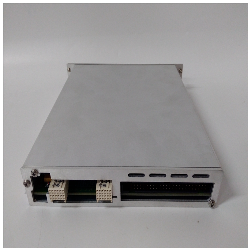
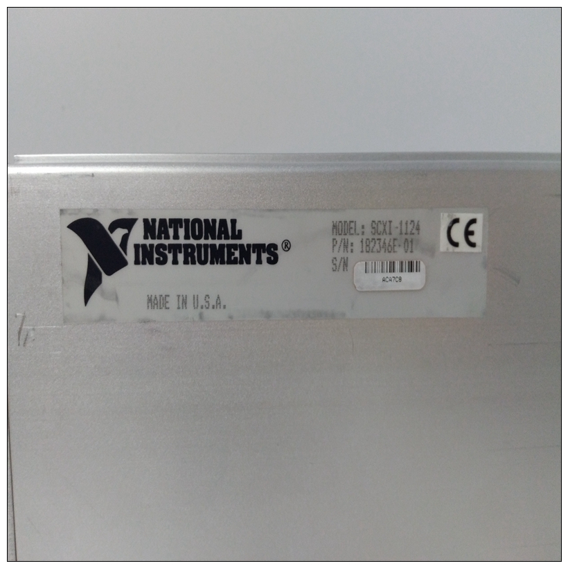
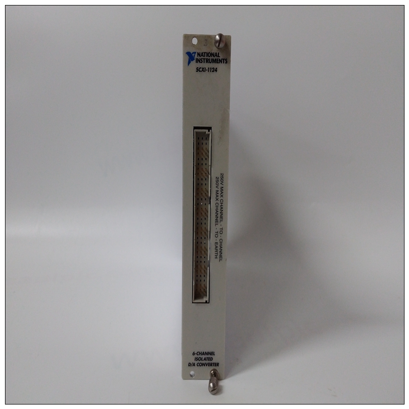
NI SCXI-1124模拟输出模块用于SCXI的6通道模拟输出模块 - SCXI‑1124是用于DC(低带宽)电压或电流信号的隔离源。 您可以针对电压或电流输出配置每个独立隔离的数模转换器(DAC)通道。 对于电压,可选择三个单极或三个双极范围中的任一个。 软件可配置的SCXI‑1124具有板载EEPROM,用于存储校准常数。 它是需要通过隔离电压或电流输出来控制过程的应用的理想选择。


NI SCXI-1124模拟输出模块MEbus中断确认映射VMEbus将中断确认周期与通过激活IACK*信号线进行其他循环。它还指定了使用A03-A01确认的液位。VMEchip监控这些线路,并在收到IACKIN*后,通过如果IACKOUT*在已确认的级别,或者通过返回状态/ID向量(如果是)。MVME147可以处理由其拥有VMEchip。介绍本章提供了编程所需的信息外围通道控制器(PCC)和VMEchip。编程外围通道控制器这些部分包含PCC内部寄存器的说明以及每个寄存器内的位分配。所有寄存器可能是作为字节写入或读取。某些限制适用于位集和清除如有指示,则不应使用说明。一PCC的整体视图如表4-1所示。请注意,在8位PCC寄存器定义的表中下面,底线中的字符定义寄存器位上可能的操作如下:R该位是只读状态位。该位可读写。C将1写入该位将其清除。该位读数为0。R/C该位可读。将1写入该位会将其清除。
VMEbus Interrupt Acknowledge Map
The VMEbus distinguishes interrupt acknowledge cycles from
other cycles by activating the IACK* signal line. It also specifies the
level that is being acknowledged using A03-A01. The VMEchip
monitors these lines and after receiving IACKIN*, it responds by
asserting IACKOUT* if it was not generating an interrupt at the
acknowledged level, or by returning a status/ID vector if it was.
The MVME147 may handle a VMEbus interrupt generated by its
own VMEchip.Introduction
This chapter provides the information needed to program the
Peripheral Channel Controller (PCC) and the VMEchip.
Programming the Peripheral Channel
Controller
These sections contain a description of the PCC internal registers
and the bit assignments within each register. All registers may be
written or read as bytes. Some restrictions apply to bit set and clear
instructions and they should not be used, where indicated. An
overall view of the PCC is shown in Table 4-1.
Note In the tables for the 8-bit PCC register definitions that
follow, the characters in the bottom line define the
operations possible on the register bits, as follows:
R This bit is a read-only status bit.
R/W This bit is readable and writable.
C Writing a 1 to this bit clears it. This bit reads 0.
R/C This bit is readable. Writing a 1 to this bit clears it.


