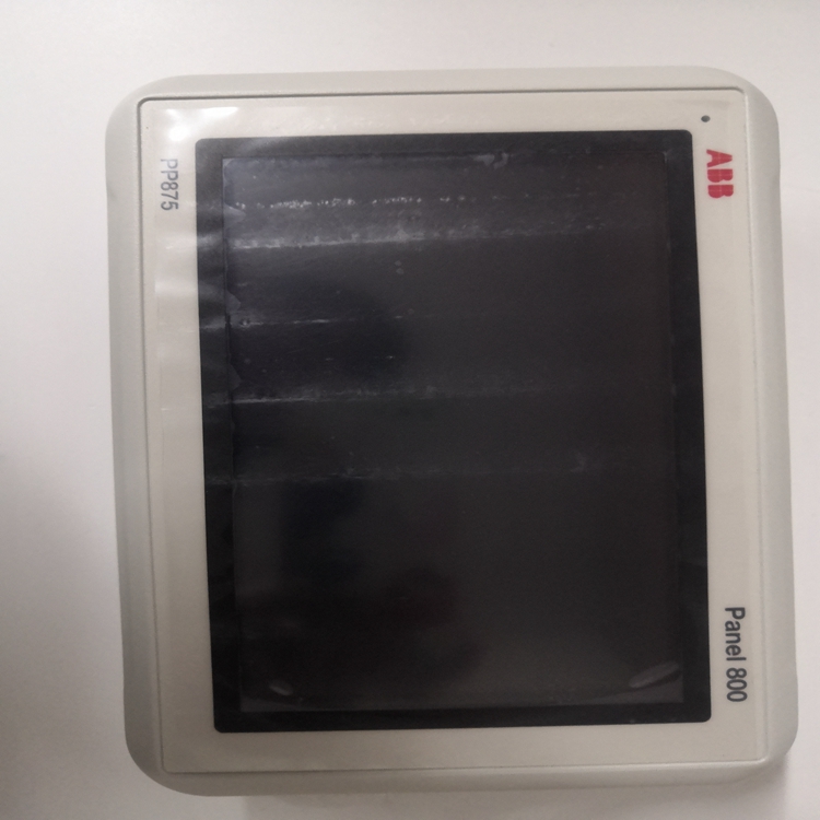
ABB触摸屏PP875 3BSE092977R1操作使用过程
除主功能外,PROFIBUS网关还执行多种附加功能,包括在以下章节中介绍。
5.1固件下载包含装置整个应用软件代码的固件存储在非易失性FlashEPROM中。可以通过服务端口加载新固件版本。通过串行链路下载使用终端。exe PC程序,可以通过串行链路从连接的PC加载新固件通过服务接口。
5.2故障保护
现场总线监督
现场总线上的通信由MCU使用超时机制进行监控。网关循环向MCU发送消息(nvoFailsafe)。故障情况已定义,因为MCU尚未在一定时间内从网关接收到消息(GW参数:Failsafe Heartbeat,MCU参数:故障保护超时)。在故障情况下,MCU进入配置状态。如果参数“Failsafe超时PLC”未激活,现场总线立即启动监控。

请注意:PR 112和ITS不提供故障保护机制。
PROFIBUS和现场总线的监控PROFIBUS上的通信由网关使用超时机制进行监控,即故障
当PCS未将PROFIBUS写入输出表的字节0、位0循环设置为1时,可识别这种情况。
可以配置此超时值(故障保护超时PLC)。网关通过以下方式响应故障情况通过LON网络向每个现场设备发送消息(nvoFailsafe=激活)。
之后现场设备进入配置状态。
在此PCS或PROFIBUS故障总线监控启动后再次设置位0。
5.3开关设备寿命清单为了监督LON网络上其他单元的网关和MMI的可用性电台在网络上周期性地发送心跳消息。每个开关设备单元都会收到此消息生成生命列表,生命列表会周期性更新。一个开关设备单元将此列传播到所有现场设备(ITS除外)。生命列表也出现在PROFIBUS读取输入表中。
寿命清单中每个开关设备单元站的位置可通过CA优先级进行配置。循环时间(SU生命信号心跳)、超时(SU生命信号超时)和心跳(SU寿命列表心跳)是可配置。智能层交换机是ABB SlimLine交换机保险丝集成传感器和基于微处理器测量和监视用电子设备LON是LonWorks网络的缩写。A.LON的变化被用作INSUM系统
In addition to the main function, PROFIBUS Gateway performs a variety of additional functions, which are
described in the following chapters.
5.1 Firmware-Download
The Firmware containing the whole application software code of the units is stored in a non-volatile FlashEPROM. A new firmware version can be loaded via service port.
Download via the Serial Link
Using terminal.exe PC program, the new firmware can be loaded from a connected PC via the serial link
through the service interface.
5.2 Failsafe
Supervision of field bus
The communication on the field bus is supervised by the MCU using a timeout-mechanism. The gateway
sends cyclically a message (nvoFailsafe) to the MCU. The fault situation is defined, as a MCU has not
received a message from gateway for a certain time (GW Parameter: Failsafe Heartbeat, MCU parameter:
Failsafe Timeout). In a fault situation the MCU goes into configured state. In case parameter "Failsafe
timeout PLC" is not activated supervision of field bus starts immediately.
Please note: Failsafe mechanism is not available for PR 112 and ITS.
Supervision of the PROFIBUS and fieldbus
The communication on the PROFIBUS is supervised by gateway using a timeout-mechanism , i.e. a fault
situation is recognised when byte 0, bit 0 of PROFIBUS Write Output Table is not set cyclic by PCS to 1.
This timeout value (Failsafe timeout PLC) can be configured. The Gateway responds the fault situation by
sending of a message (nvoFailsafe= activated) via the LON-network to each field device. Afterwards the
field device goes into configured state. After this PCS or PROFIBUS failure bus supervision starts by
setting of bit 0 again.
5.3 Life List for Switchgear Units
To supervise the availability of the Gateways and the MMIs for other units on the LON network these
stations cyclically send a heartbeat message on the net. Every switchgear unit receives this message and
generates a Life List, which is cyclically updated. One switchgear unit propagates this list to all field devices
(except ITS). Life List appears in PROFIBUS Read Input Table too.
Position of every switchgear unit station in Life List is configurable by CA Priority. The cycle time (SU
Lifesign Heartbeat), the timeout (SU Lifesign Timeout) and heartbeat (SU Lifelist Heartbeat) are
configurable.


