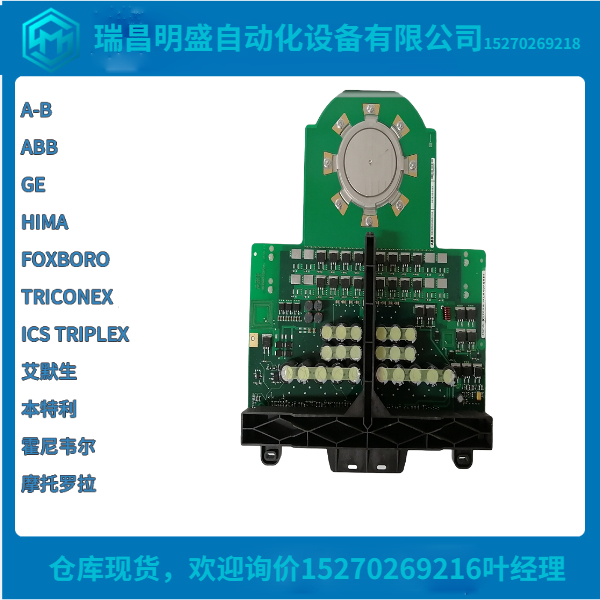
IGCT可控硅5SHX1960L0004模块化发展
SIE中的控制器标签。DATA保存要在处理器和MVI56E-SIE模块。此读写数据在处理器之间传输和模块为“页面”或块,数据长度不超过200个字。SIE.data的数据类型。ReadData和SIE.DATA。WriteData控制器标记数组是包含可变元素数的整数数组。SIE.DATA.读取数据ReadData是一个控制器标记数组,可自动调整以匹配输入的值在配置的读取寄存器计数(第35页)参数中。为了便于使用,这个数组应该是200个单词的倍数。此数据翻至从模块到处理器,每次200字。梯形图逻辑放置数据

接收到ReadData数组中的正确位置。此数据用于状态和处理器梯形图逻辑中的控制。
ReadData数组与模块的ReadData区域的内容相关内部数据库。要查看模块内部数据库中的实际寄存器,请访问从ProSoft Configuration Builder的诊断菜单中显示数据库。更多信息,请参阅PCB Diagnostics WriteData部分,它是一个控制器标记数组,可自动调整以匹配输入的值在配置的写入寄存器计数(第36页)参数中。为了便于使用,这个数组应该是200个单词的倍数。此数据上翻至从处理器到模块,每次200字。梯形图逻辑将写入数据传输到输出图像以传输到模块。此数据从处理器向模块发送状态和控制信息,以便在上的其他节点中使用网络WriteData数组与模块的“写入数据”区域的内容相关内部数据库。
要查看模块内部数据库中的实际寄存器,请访问从ProSoft Configuration Builder的诊断菜单中显示数据库。更多信息,请参阅PCB诊断诊断和故障排除部分
该模块提供以下诊断和故障排除信息
形式:
模块前面的LED状态指示灯提供有关模块的信息地位
模块中包含的状态数据可以在ProSoft Configuration Builder中查看通过以太网端口。
状态数据值从模块传输到处理器。
The controller tags in SIE.DATA hold data to be transferred between the processor and
the MVI56E-SIE module. This read and write data is transferred between the processor
and module as "pages," or blocks, of data up to 200 words long.
The data types for the SIE.DATA.ReadData and SIE.DATA.WriteData controller tag
arrays are integer arrays containing variable numbers of elements.
SIE.DATA.ReadData
ReadData is a controller tag array that automatically adjusts to match the value entered
in the Read Register Count (page 35) parameter of the configuration. For ease of use,
this array should be dimensioned as a multiple of 200 words. This data is paged up to
200 words at a time from the module to the processor. The ladder logic places the data
received into the proper position in the ReadData array. This data is used for status and
control in the processor ladder logic.
The ReadData array is related to the contents of the Read Data area of the module's
internal database. To view the actual registers in the module's internal database, access
the database display from ProSoft Configuration Builder's Diagnostics menu. For more
information, see the section on PCB Diagnostics WriteData is a controller tag array that automatically adjusts to match the value entered
in the Write Register Count (page 36) parameter of the configuration. For ease of use,
this array should be dimensioned as a multiple of 200 words. This data is paged up to
200 words at a time from the processor to the module. The ladder logic places the write
data into the output image for transfer to the module. This data is passed from the
processor to the module for status and control information for use in other nodes on the
network.The WriteData array is related to the contents of the Write Data area of the module's
internal database. To view the actual registers in the module's internal database, access
the database display from ProSoft Configuration Builder's Diagnostics menu. For more
information, see the section on PCB Diagnostics Diagnostics and Troubleshooting
The module provides information on diagnostics and troubleshooting in the following
forms:
LED status indicators on the front of the module provide information on the module’s
status.
Status data contained in the module can be viewed in ProSoft Configuration Builder
through the Ethernet port.
Status data values are transferred from the module to the processor.


