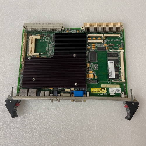
GE通用电气VMIVME-3125A-200000卡件产生
下行斜坡发生器[4]从给定的阶梯输入信号生成斜坡形输出信号。这个该信号的时间常数可单独调整:
上下方向通过两个电位计。指定的斜坡时间是指100%的命令值步长,并且可以是大约1s或5s,取决于通过DIL开关2的设置)。如果小于100%的命令值步长切换到斜坡发生器输入,或者如果衰减器[3]有效,斜坡时间将相应地更短。对于类型VT-VSPA1-1,以下适用:外部“上升/下降”触点,向上和向下斜坡时间可单独设置为其最小值(约30ms)。
对于VT-VSPA1K-1型,以下适用:外部“斜坡关闭”触点,向上和向下斜坡时间可设置为其最小值(约30ms)。斜坡发生器[4]输出信号被转发到求和放大器[5]作为电流指令值。在这里+6 V的电压对应于指令值为100%。

在求和放大器[5]中
特性曲线生成器[6或7]添加到命令值(可通过DIL选择开关2)取决于要控制的阀)。这个电流指令值可通过可连接低通滤波。电流输出级[9]由电流控制器[8]控制。在电流控制器中,电流指令值还被调制使用时钟发生器信号[10](频率可以使用DIL开关2编程)。在阀螺线管中,时钟实际电流值的作用类似于恒定电流
具有叠加的抖动信号。VT-VSPA1-1型具有:内部命令值和实际值。
对于命令值:+6 V,以下为真:≙ 100%
以下为实际值:1 mV≙ 1毫安
“运行准备就绪”信号输出,“H2”LED
前板上(带VSPA1-1)或“H2”LED
(带VSPA1K-1)在以下情况下点亮:
▶ 电磁线圈导体不存在短路,并且输出级没有过载,
▶ 命令值可用(电缆断裂检测),
▶ 电磁线圈导线没有电缆断裂。对于VT-VSPA1-1型(组件系列10)
BR22开关必须设置为“ON”,并且必须将“R130”电位计旋转到左侧止动位置,以便设置校正特性曲线。
VT-VSPA1-1型(来自部件系列11)和VT-VSPA1K-1型,开关S21和S22没有任何效应无需操作“Zw”电位计。
The down-stream ramp generator [4] generates a rampshaped output signal from a given stepped input signal. The
time constant of this signal can be separately adjusted for
the upwards and downwards direction by means of two
potentiometers. The specified ramp time refers to a command value step of 100 % and may be approx. 1 s or 5 s,
depending on the setting by means of a DIL switch 2). If
a command value step of less than 100 % is switched to the
ramp generator input or if the attenuator [3] is effective,
the ramp time will be correspondingly shorter.
To type VT-VSPA1-1, the following applies: By means of the
external "ramp up/down off" contacts, the upwards and
downwards ramp times can be separately set to their minimum value (approx. 30 ms).
To type VT-VSPA1K-1, the following applies: By means of
the external "ramp off" contact, the upwards and downwards ramp times can be set to their minimum value
(approx. 30 ms) together.The ramp generator [4] output signal is forwarded to the
summing amplifier [5] as current command value. Here,
a voltage of +6 V corresponds to a command value
of 100 %.
In the summing amplifier [5], the output signals of the
characteristic curve generators [6 or 7] are added to the
command value (can be selected by means of DIL
switches 2) depending on the valve to be controlled). The
current command value can be filtered by means of a connectible low pass. The current output stage [9] is controlled using the current controller [8]. In the current controller, the current command value is moreover modulated
with the clock generator signal [10] (frequency can be
programmed using the DIL switch 2)). In the valve solenoid,
the clocked actual current value acts like a constant current
with superimposed dither signal. Type VT-VSPA1-1 has
measuring sockets for the internal command value and the
actual value.
The following is true for the command value: +6 V ≙ 100 %
The following is true for the actual value: 1 mV ≙ 1 mA
The "ready for operation" signal is output and the "H2" LED
on the front plate (with VSPA1-1) or the "H2" LED
(with VSPA1K-1) is illuminated if:
▶ there is no short-circuit of the solenoid conductors and
no overload of the output stage,
▶ a command value is available (cable break detection),
▶ there is no cable break of the solenoid conductor.With type VT-VSPA1-1 (component series 10), the
BR22 switch must be set to "ON" and the "R130" potentiometer must be rotated to the left stop in order to set the
correct characteristic curve.
With type VT-VSPA1-1 (from component series 11) and
type VT-VSPA1K-1, switches S21 and S22 do not have any
effect. The "Zw" potentiometer does not have to be operated.


