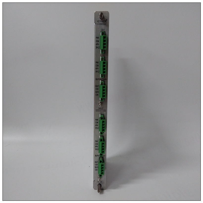
BENTLY 125800-01 3500/25速度监测器模块
关闭所有设备电源并断开电源来自交流电源的电缆。2、按照设备用户手册中的说明卸下机箱手册3.从以下位置的相应卡槽中卸下填充板:机箱的前部和后部(如果机箱有后部卡保持架)。MVME177模块需要来自两个P1的电源和P2。它可以安装在任何双高未使用的卡中插槽,如果未配置为系统控制器。如果MVME177配置为系统控制器,必须安装在最左侧的卡插槽(插槽1)中,以正确启动总线授予菊花链,并使IACK菊花链驱动器。


BENTLY 125800-01 3500/25速度监测器模块将MVME177安装在底盘。您可以将MVME712x安装在前部或机箱后部。系统中的其他模块可能需要移动以留出MVME712M的空间,MVME712M具有双宽前面板4、小心地将MVME177模块滑入卡槽。是确保模块正确座入P1和P2背板上的连接器。不要损坏或弯曲接头针脚。用提供的螺钉将模块固定在机箱中,使其与横向安装件接触良好减少RFI排放的轨道。5.将IACK和BG跳线从MVME177所在卡槽的机箱底板安装。6.将P2适配器板和指定电缆连接到MVME177在MVME177插槽的背板上的P2处,至与(可选)终端或其他外围设备配合EIA-232-D串行端口、并行端口、SCSI端口和LAN以太网端口。请参阅相关手册中列出的手册有关安装的信息,请参阅第1章中的文档P2适配器板和MVME712x转换模块。(一些连接图在单板计算机中程序员参考指南)。部分电缆未提供使用MVME712x模块,因此制造或由用户提供。(摩托罗拉建议使用屏蔽所有连接到外围设备的电缆,以最小化辐射)。将外围设备连接到电缆。详细的的EIA-232-D信号信息见附录A。
7、连接用作系统控制台的终端至串行端口1上的默认调试EIA-232-D端口通过MVME712x转换的背板连接器P2单元参考单板机程序员的一些可能的连接图的参考指南。设置终端如下:❏ 每个字符8位❏ 每个字符一个停止位❏ 禁用奇偶校验(无奇偶校验)
❏ 波特率9600波特(MVME177的默认波特率通电时的端口)通电后,调试端口的波特率可以通过使用177Bug调试器。
Turn all equipment power OFF and disconnect the power
cable from the AC power source. 2. Remove chassis cover as instructed in the equipment user's
manual.
3. Remove the filler panel(s) from the appropriate card slot(s) at
the front and rear of the chassis (if the chassis has a rear card
cage). The MVME177 module requires power from both P1
and P2. It may be installed in any double-height unused card
slot, if it is not configured as system controller. If the
MVME177 is configured as system controller, it must be
installed in the leftmost card slot (slot 1) to correctly initiate
the bus-grant daisy-chain and to have proper operation of the
IACK-daisy-chain driver. Install the MVME177 in the front of
the chassis. You can install the MVME712x in the front or the
rear of the chassis. Other modules in the system may have to
be moved to allow space for the MVME712M which has a
double-wide front panel.
4. Carefully slide the MVME177 module into the card slot. Be
sure the module is seated properly into the P1 and P2
connectors on the backplane. Do not damage or bend
connector pins. Fasten the module in the chassis with screws provided, making good contact with the transverse mounting
rails to minimize RFI emissions.
5. Remove IACK and BG jumpers from the header on the
chassis backplane for the card slot in which the MVME177 is
installed.
6. Connect the P2 Adapter Board and specified cable(s) to the
MVME177 at P2 on the backplane at the MVME177 slot, to
mate with (optional) terminals or other peripherals at the
EIA-232-D serial ports, parallel port, SCSI ports, and LAN
Ethernet port. Refer to the manuals listed in Related
Documentation in Chapter 1 for information on installing the
P2 Adapter Board and the MVME712x transition module(s).
(Some connection diagrams are in the Single Board Computers
Programmer's Reference Guide). Some cable(s) are not provided
with the MVME712x module(s), and therefore are made or
provided by the user. (Motorola recommends using shielded
cables for all connections to peripherals to minimize
radiation). Connect the peripherals to the cable(s). Detailed
information on the EIA-232-D signals supported is found in
Appendix A.
7. Connect the terminal to be used as the 177Bug system console
to the default debug EIA-232-D port at serial port 1 on
backplane connector P2 through an MVME712x transition
module. Refer to the Single Board Computers Programmer's
Reference Guide for some possible connection diagrams. Set up
the terminal as follows:
❏ Eight bits per character
❏ One stop bit per character
❏ Parity disabled (no parity)
❏ Baud rate 9600 baud (default baud rate of MVME177
ports at power-up)
After power-up, the baud rate of the debug port can be
reconfigured by using the Port Format (PF) command of the
177Bug debugger.


