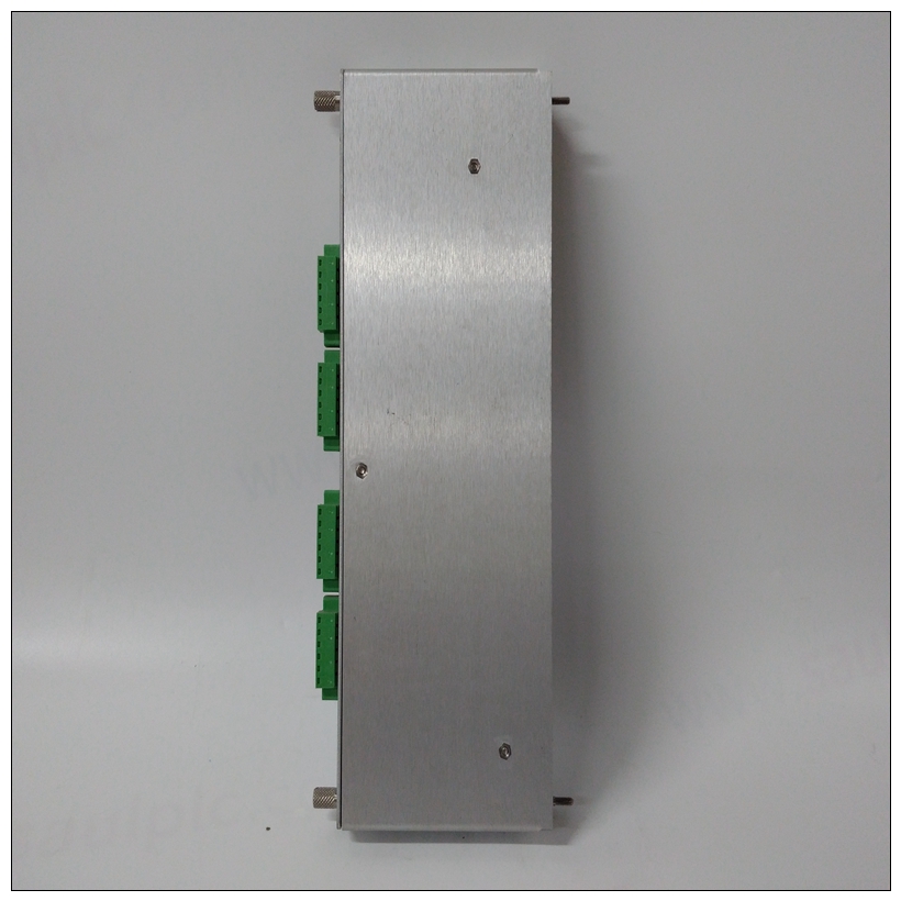
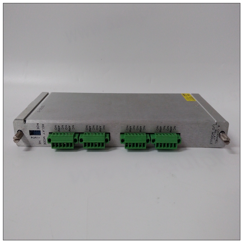
BENTLY 125720-01 3500/32通道继电器模块
启动程序概述下表列出了您之前需要做的事情你可以使用这个板,在哪里可以找到你需要的信息执行每个步骤。一定要阅读这整章,并阅读所有内容开始前的注意事项。硬件准备选择所需配置并确保对于MVME177,可能需要进行某些选项修改安装前。MVME177为以下各项提供软件控制:大多数选项。有些选项无法在软件中完成,因此由标题上的跳线完成。


BENTLY 125720-01 3500/32通道继电器模块大多数其他修改已完成通过在MVME177完成后在控制寄存器中设置位安装在系统中。(MVME177寄存器在第4章和/或在单板机程序员的参考指南见第1章的相关文件)。开关、跳线头、连接器和LED的位置MVME177上的指示器如图2-1所示。MVME177已经过工厂测试,并随以下章节介绍了工厂跳线设置。这个MVME177使用其所需和工厂安装的调试进行操作监视器,MVME177Bug(177Bug),带有这些工厂跳线设置。可以设置:❏ 标题上的通用可读跳线(J1)
❏ SRAM备用电源选择标题(J2)(可选)❏ 系统控制器标题(J6)❏ 热敏引脚(J7)❏ EPROM/闪存配置跳线(J8)❏ 串行端口4时钟配置选择标头(J9和J10)
请参阅表2-2,为每个标头配置跳线设置。标头J1上的通用可读跳线可以读取为输入/输出控制
VMEchip2 LCSR中的寄存器3(位于$FFF40088,位0-7)(参见第4章,VMEchip2)。跳线断开时,位值读取为1,读取为0当跳线接通时。2.MVME177上,移除了板ID和位的引脚7和8(位3)保留值。
Overview of Start-up Procedure
The following list identifies the things you will need to do before
you can use this board, and where to find the information you need
to perform each step. Be sure to read this entire chapter and read all
Caution notes before beginning. Hardware Preparation
To select the desired configuration and ensure proper operation of
the MVME177, certain option modifications may be necessary
before installation. The MVME177 provides software control for
most of these options. Some options cannot be done in software, so
are done by jumpers on headers. Most other modifications are done
by setting bits in control registers after the MVME177 has been
installed in a system. (The MVME177 registers are described in
Chapter 4, and/or in the Single Board Computers Programmer's
Reference Guide as listed in Related Documentation in Chapter 1).
The location of switches, jumper headers, connectors, and LED
indicators on the MVME177 is illustrated in Figure 2-1.
The MVME177 has been factory tested and is shipped with the
factory jumper settings described in the following sections. The
MVME177 operates with its required and factory-installed Debug
Monitor, MVME177Bug (177Bug), with these factory jumper
settings.
Settings can be made for:
❏ General purpose readable jumpers on header (J1)
❏ SRAM backup power source select header (J2) (optional)
❏ System controller header (J6)
❏ Thermal sensing pins (J7)
❏ EPROM/Flash configuration jumper (J8)
❏ Serial port 4 clock configuration select headers (J9 and J10)
Refer to Table 2-2 to configure the jumper settings for each headerThe general purpose readable jumpers on header J1 can be read as I/O control
register 3 (at $FFF40088, bits 0-7) in the VMEchip2 LCSR (see Chapter 4,
VMEchip2). The bit values are read as a 1 when the jumper is off, and as a 0
when the jumper is on.
2. On the MVME177, pins 7 and 8 (bit 3) are removed for board ID and the bit
value is reserved.


