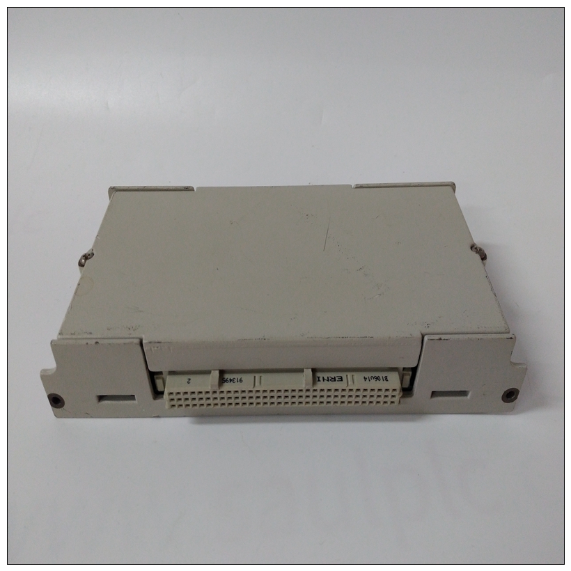
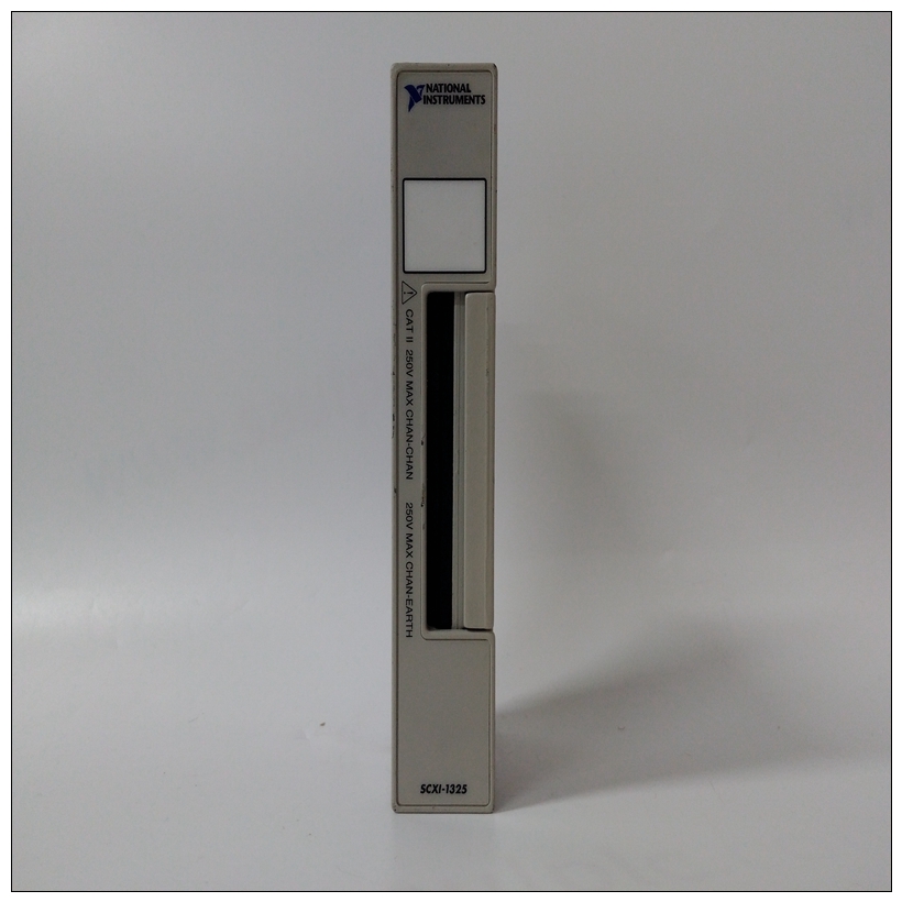
NI SCXI-1325电压输入模块,SCXI-1325配置手册
执行这些操作之前,请关闭系统电源程序。在打开前未能关闭电源外壳可能导致人身伤害或设备损坏设备危险电压、电流和能级为存在于机箱中。上可能存在危险电压即使在电源开关关闭时,电源开关端子也是如此。切勿在卸下盖子的情况下操作系统。总是在给系统通电之前,请更换盖子。准备董事会产生所需的配置并确保MVME172LX,您可能需要执行某些硬件修改安装模块之前。


NI SCXI-1325电压输入模块MVME172LX提供了对大多数选项的软件控制:通过在系统中安装模块后,在控制寄存器中设置位可以修改其配置。(描述了MVME172LX寄存器在第3章的ENV–Set环境和/或MVME172 VME中“相关”中列出的嵌入式控制器程序员参考指南附录E中的“文件”)
然而,有些选项不是软件可编程的。这些选项包括通过手动安装或拆除收割台跳线或基板上的接口模块。MVME172LX配置图1-1说明了跳线头、连接器和MVME172LX上的各种其他组件。手动配置下表列出了MVME172LX上的跳线头(带有默认设置括在括号中)。系统控制器选择标题(J1)MVME172LX在工厂配置为VMEbus系统控制器(即,跨接导线安装在收割台J1的针脚1和2之间)。拆下J1如果MVME172LX不是系统控制器,则跳线。请注意当MVME172LX用作系统控制器时,SCONLED亮起。注:MVME172s没有可选的VMEbus接口(即。,如果没有VMEchip2 ASIC),则可以安装或在不影响正常操作的情况下移除
Turn the system’s power off before you perform these
procedures. Failure to turn the power off before opening the
enclosure can result in personal injury or damage to the
equipment. Hazardous voltage, current, and energy levels are
present in the chassis. Hazardous voltages may be present on
power switch terminals even when the power switch is off.
Never operate the system with the cover removed. Always
replace the cover before powering up the system.
Preparing the Board
To produce the desired configuration and ensure proper operation of the
MVME172LX, you may need to carry out certain hardware modifications
before installing the module.
The MVME172LX provides software control over most options: by
setting bits in control registers after installing the module in a system, you
can modify its configuration. (The MVME172LX registers are described
in Chapter 3 under ENV – Set Environment, and/or in the MVME172 VME
Embedded Controller Programmer's Reference Guide as listed in “Related
Documentation” in Appendix E.)
Some options, however, are not software-programmable. Such options are
controlled through manual installation or removal of header jumpers or
interface modules on the base board.
MVME172LX Configuration
Figure 1-1 illustrates the placement of the jumper headers, connectors, and
various other components on the MVME172LX. Manually configurable
jumper headers on the MVME172LX are listed in the following table (with
default settings enclosed in brackets).System Controller Select Header (J1)
The MVME172LX is factory-configured as a VMEbus system controller
(i.e., a jumper is installed across pins 1 and 2 of header J1). Remove the J1
jumper if the MVME172LX is not to be the system controller. Note that
when the MVME172LX is functioning as system controller, the SCON
LED is turned on.
Note On MVME172s without the optional VMEbus interface (i.e.,
with no VMEchip2 ASIC), the jumper may be installed or
removed without affecting normal operation


