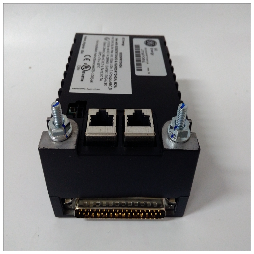
IS220PRTDH1A 363A4940CSP6燃机通用卡件,GE使用数量
软件可编程硬件中断8个软件可编程硬件中断由VMEchip2。这些中断允许软件创建硬件中断。请参阅MVME162嵌入式控制器中的VMEchip2说明详细编程信息的程序员参考指南。本地总线超时MVME162在VMEchip2和MCchip中提供超时功能对于本地总线。当计时器启用且本地总线访问超时时,传输错误确认(TEA)信号被发送到本地总线主机。这个超时值可由软件选择8微秒、64微秒、256微秒或无限长。


IS220PRTDH1A 363A4940CSP6燃机通用卡件本地总线计时器在VMEbus绑定周期内不工作。VME总线绑定周期由VMEbus访问计时器和VMEbus全局计时器计时计时器。请参阅MVME162中的VMEchip2和MCchip说明嵌入式控制器程序员详细编程参考指南信息MCchip还为MVME162提供了本地总线超时逻辑,而无需可选的VMEbus接口(即,没有VMEchip2)。定时性能本节提供MVME162的性能信息。这个MVME162的设计工作频率为25 MHz。本地总线到DRAM循环时间DRAM基址、阵列大小和设备大小可编程。这个如果DRAM大小需要八个物理设备(即,当内存阵列大小为4MB时DRAM技术是每个设备4Mbit;或者当内存阵列大小为16MB时DRAM技术是每台设备16Mbit。)奇偶校验和奇偶异常操作也可编程。DRAM阵列大小和设备大小在DRAM空间大小寄存器中初始化。TEA是MC68040总线错误事务信号。“配茶”指示如果发生DRAM奇偶校验错误,则会发生总线错误周期检测。EPROM/闪存循环时间EPROM/闪存周期时间可在3到10个总线时钟/字节之间编程(4字节=12到40)。(实际循环时间可能因设备而异速度。)数据传输为32位宽。参考MVME162嵌入式控制器程序员参考指南。SCSI传输MVME162包括一个与DMA的SCSI大容量存储总线接口控制器。SCSI DMA控制器使用FIFO缓冲区连接8位SCSI总线到32位本地总线。FIFO缓冲区允许SCSI DMA控制器以四个长字突发有效地将数据传输到本地总线。Software-Programmable Hardware Interrupts
Eight software-programmable hardware interrupts are provided by the
VMEchip2. These interrupts allow software to create a hardware interrupt.
Refer to the VMEchip2 desciption in the MVME162 Embedded Controller
Programmer’s Reference Guide for detailed programming information.
Local Bus Timeout
The MVME162 provides timeout functions in the VMEchip2 and the MCchip
for the local bus. When the timer is enabled and a local bus access times out,
a Transfer Error Acknowledge (TEA) signal is sent to the local bus master. The
timeout value is selectable by software for 8 µsec, 64 µsec, 256 µsec, or infinity.
The local bus timer does not operate during VMEbus bound cycles. VMEbus
bound cycles are timed by the VMEbus access timer and the VMEbus global
timer. Refer to the VMEchip2 and MCchip descriptions in the MVME162
Embedded Controller Programmer’s Reference Guide for detailed programming
information.
The MCchip also provides local bus timeout logic for MVME162s without the
optional VMEbus interface (i.e., without the VMEchip2).
Timing Performance
This section provides performance information for the MVME162. The
MVME162 is designed to operate at 25 MHz.Local Bus to DRAM Cycle Times
The DRAM base address, array size, and device size are programmable. The
DRAM controller assumes an interleaved architecture if the DRAM size
requires eight physical devices (that is, when memory array size is 4MB and
DRAM technology is 4 Mbits per device; or when memory array size is 16MB
and DRAM technology is 16 Mbits per device.)
Parity checking and parity exception action is also programmable. The DRAM
array size and device size are initialized in the DRAM Space Size Register.
TEA is the MC68040 bus error transaction signal. "With TEA"
indicates that a bus error cycle occurs if a DRAM parity error was
detected.
EPROM/Flash Cycle Times
The EPROM/Flash cycle time is programmable from 3 to 10 bus clocks/byte
(4 bytes = 12 to 40). (The actual cycle time may vary depending on the device
speed.) The data transfers are 32 bits wide. Refer to the MVME162 Embedded
Controller Programmer’s Reference Guide.
SCSI Transfers
The MVME162 includes an SCSI mass storage bus interface with DMA
controller. The SCSI DMA controller uses a FIFO buffer to interface the 8-bit
SCSI bus to the 32-bit local bus. The FIFO buffer allows the SCSI DMA
controller to efficiently transfer data to the local bus in four longword bursts.


