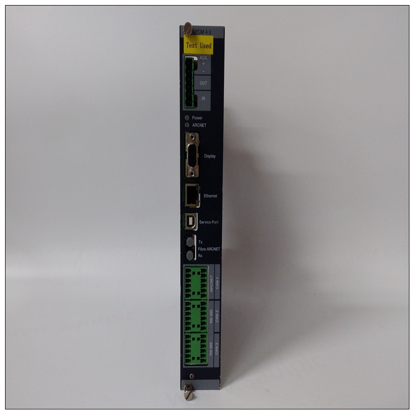
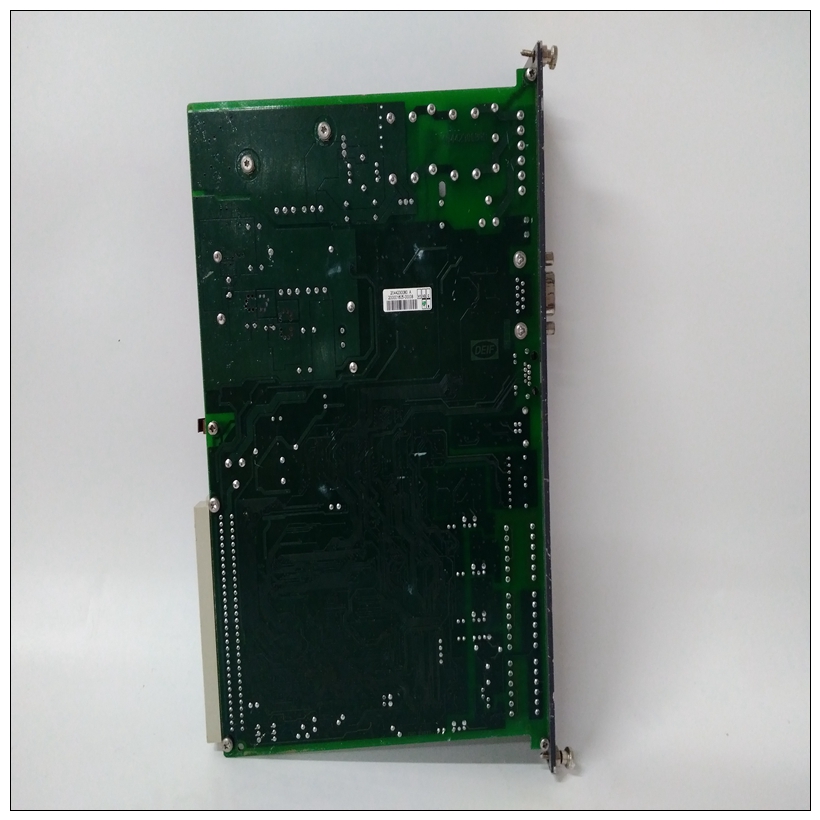
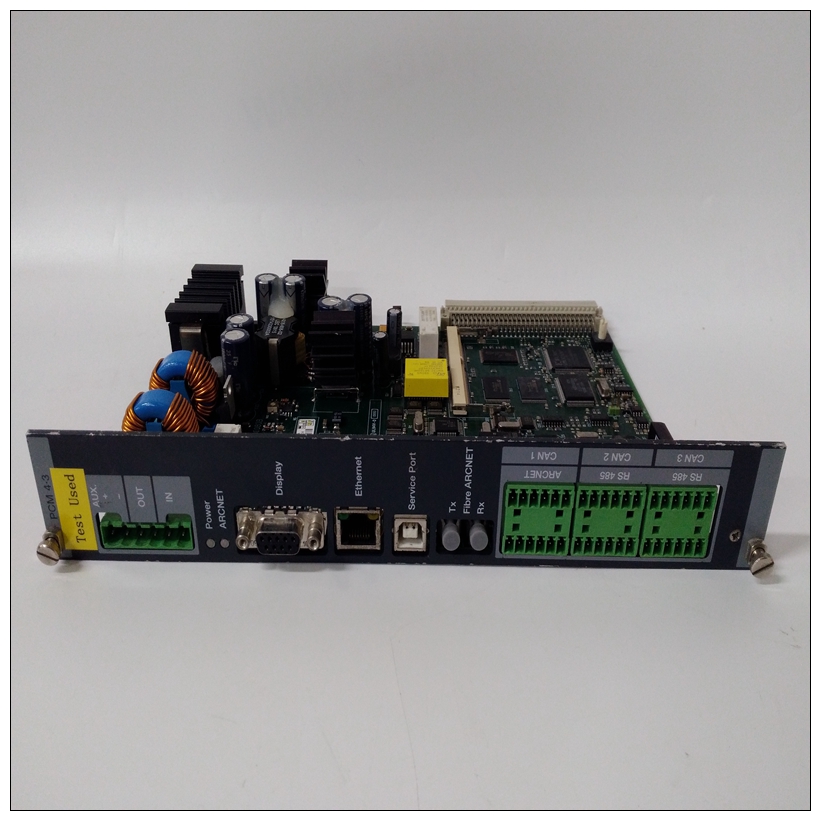
DEIF PCM4.3控制通讯板,PCM4.3配置说明
应始终清除SLVD16。将SLVD16设置为1将VMEchip从设备配置为仅提供D08(EO)和D16数据传输能力。通常在本地总线只有16位宽。将SLVD16位清除为0配置VMEchip从机提供D08(EO)、D16和D32/UAT数据传输能力。该位由SYSRESET清除。位5设置SLVWP位加速VMEbus写入板载DRAM。


DEIF PCM4.3控制通讯板当设置SLVWP(从写过账)时,VMEbus板载DRAM的写入周期由VMEchip,然后将数据写入DRAM。这允许VMEbus主机快速结束其循环,放置VMEchip完成板载写入的负担DRAM本身。该位由SYSRESET清除。位7将SLVEN设置为1使其他VMEbus主机能够访问MVME147机载DRAM。该位由SYSRESET清除。将ARBTO设置为1将启用VMEbus仲裁计时器。这个如果未激活,VMEbus仲裁计时器将激活BBSY*MVME147仲裁器发出总线授权后410µs内。这个计时器根据VMEbus中的规定停用BBSY*规格这导致仲裁人对任何未决案件进行仲裁请求公共汽车。该位由SYSRESET设置为1。该寄存器允许软件配置VMEbus主机必须使用的地址修饰符代码访问机载DRAM。寄存器的8位分为三组。至少一个位在每个组中必须设置,否则地址忽略主控形状使用的修饰符。地址位7位6位5位4位3位2位1位0FFFE200B超级用户扩展STND短块PRGRM数据位0-2这三个位构成配置从机的第一组AM代码。将任何位设置为1使从机能够响应以下示例中所述的循环。笔记不应设置块。这些位通过系统重置。位3-5这三个位构成第二组。将任何位设置为1使从机能够响应中所述的周期示例如下。这些位由SYSRESET清除。位6-7这两个位形成第三组。将任何位设置为1使从属设备能够响应中所述的周期
SLVD16 should always be cleared. Setting SLVD16 to 1
configures the VMEchip slave to provide only D08 (EO) and
D16 data transfer capabilities. It is typically set when the local
bus is only 16 bits wide. Clearing the SLVD16 bit to 0 configures
the VMEchip slave to provide the D08 (EO), D16, and D32/UAT
data transfer capabilities. This bit is cleared by SYSRESET.
Bit 5 Setting the SLVWP bit speeds up VMEbus writes to the onboard
DRAM. When SLVWP (slave write posting) is set, VMEbus
write cycles to the onboard DRAM are acknowledged by the
VMEchip before the data has been written into the DRAM. This
allows the VMEbus master to end its cycle quickly, placing the
burden on the VMEchip to complete the write to onboard
DRAM on its own. This bit is cleared by SYSRESET.
Bit 7 Setting SLVEN to 1 enables other VMEbus masters to access the
MVME147 onboard DRAM. This bit is cleared by SYSRESET. Setting ARBTO to 1 enables the VMEbus arbitration timer. The
VMEbus arbitration timer activates BBSY* if it is not activated
within 410 µs after the MVME147 arbiter issues a bus grant. The
timer deactivates BBSY* as specified in the VMEbus
specification. This causes the arbiter to arbitrate any pending
requests for the bus. This bit is set to 1 by SYSRESET. This register allows software to configure which
address modifier codes the VMEbus masters must use
to access the onboard DRAM. The 8 bits of the register
are organized into three groups. At least one of the bits
in each group must be set, otherwise the address
modifier used by the master is ignored.
ADDRESS BIT 7 BIT 6 BIT 5 BIT 4 BIT 3 BIT 2 BIT 1 BIT 0
FFFE200B SUPER USER EXTED STND SHORT BLOCK PRGRM DATA
R/W R/W R/W R/W R/W R/W R/W R/W
Bits 0-2 These three bits form the first group which configures the slave
AM code. Setting any of the bits to 1 enables the slave to
respond to cycles as described in the example below. Note
BLOCK should never be set. These bits are cleared by
SYSRESET.


