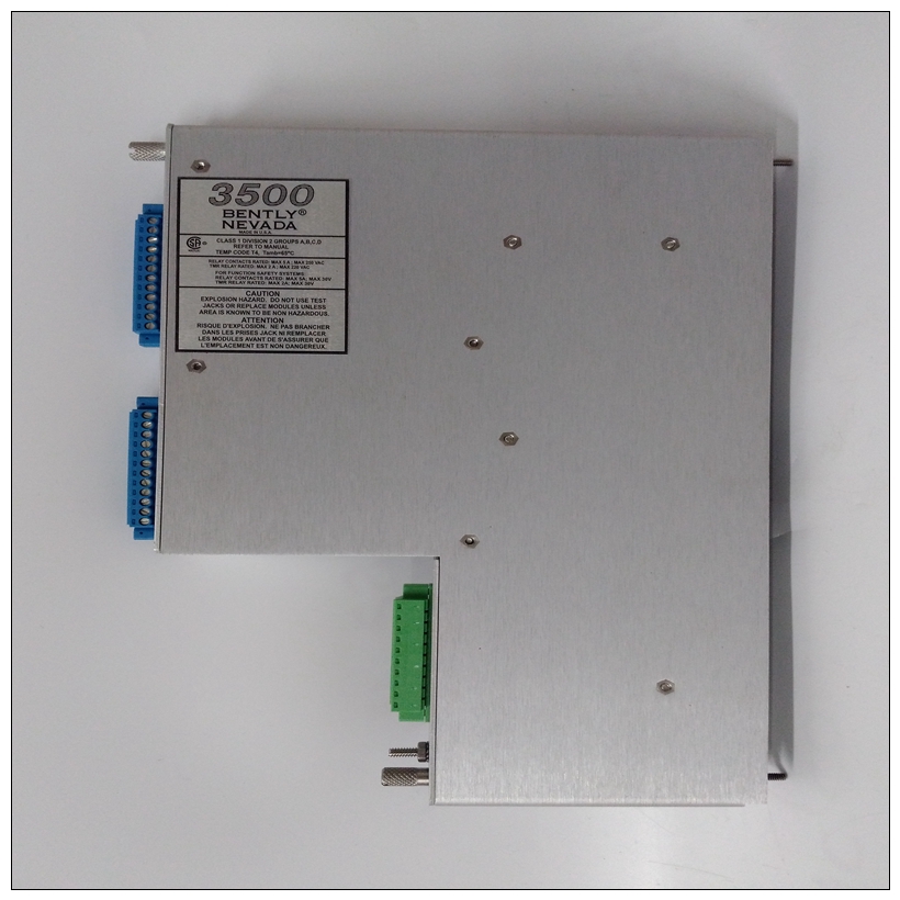
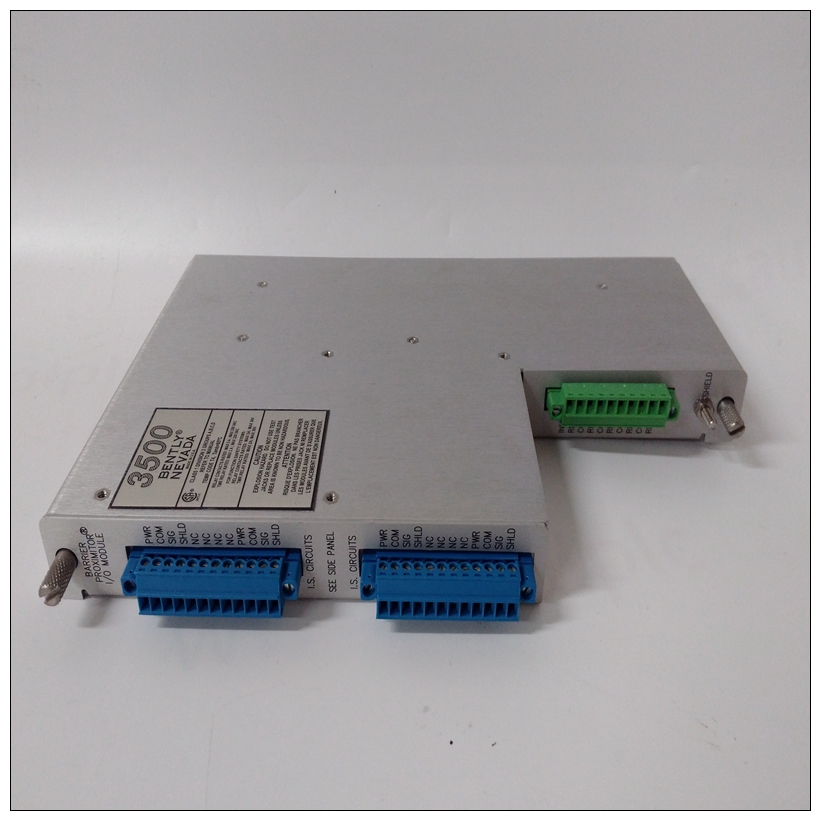
BENTLY 135489-01气体监测器,135489-01使用配置手册
系统注意事项MVME177同时从VMEbus的P1和P2供电背板。P2还用于32位的上16位数据传输,以及用于扩展寻址的上8个地址行模式MVME177将无法正常工作,除非其主要板连接到VMEbus背板的P1和P2。MVME177是作为VMEbus主机还是作为VMEbus从机,配置为32位地址和32位数据(A32/D32)。然而,它处理A16或A24设备第3章中指出的地址范围。


BENTLY 135489-01气体监测器中的D8和/或D16设备系统必须由MC68060软件处理。请参阅第3章中的内存映射。MVME177包含共享板载DRAM,其基座地址可由软件选择。车载处理器和非车载VMEbus设备在基本物理位置查看此本地DRAM地址$00000000,由MVME177BUG固件编程。这可以通过软件更改为任何其他基础住址参考单板机程序员参考详细信息指南。MVME177尝试在不存在位置,并且不是系统控制器,如果系统没有全局总线超时,MVME177永远等待VMEbus循环完成。这会导致系统挂起。只有一种情况下,系统可能缺少此功能全局总线超时:❏ MVME177不是系统控制器,并且❏ 系统中其他地方没有全局总线超时多个MVME177模块可配置为单个VME卡片固定框架。通常,硬件多处理器功能包括支持。VMEbus上的其他MPU可以:❏ 打断❏ 使残废与沟通,以及❏ 确定的操作状态处理器。GCSR集的一个寄存器包括四位作为位置监视器,允许一个MVME177处理器向其他MVME177处理器广播信号,如果任何所有八个寄存器都可以从任何本地处理器访问以及从VMEbus。MVME177为以太网LAN提供+12 Vdc电源收发器接口,通过位于MVME177模块。+12 Vdc时,+12 V LED亮起可获得的多功能开关位于二极管CR1附近。多路开关就像断路器一样,当电流过大时,断路器会自动复位移除负载。如果以太网收发器无法工作,请检查
System Considerations
The MVME177 draws power from both P1 and P2 of the VMEbus
backplane. P2 is also used for the upper 16 bits of data for 32-bit
transfers, and for the upper 8 address lines for extended addressing
mode. The MVME177 will not operate properly unless its main
board is connected to P1 and P2 of the VMEbus backplane.
Whether the MVME177 operates as a VMEbus master or as a
VMEbus slave, it is configured for 32 bits of address and for 32 bits
of data (A32/D32). However, it handles A16 or A24 devices in the
address ranges indicated in Chapter 3. D8 and/or D16 devices in the
system must be handled by the MC68060 software. Refer to the
memory maps in Chapter 3.
The MVME177 contains shared onboard DRAM whose base
address is software-selectable. Both the onboard processor and
offboard VMEbus devices see this local DRAM at base physical
address $00000000, as programmed by the MVME177Bugfirmware. This may be changed, by software, to any other base
address. Refer to the Single Board Computers Programmer's Reference
Guide for details.
If the MVME177 attempts to access offboard resources in a
nonexistent location, and is not system controller, and if the system
does not have a global bus time-out, the MVME177 waits forever for
the VMEbus cycle to complete. This causes the system to hang up.
There is only one situation in which the system might lack this
global bus time-out:
❏ The MVME177 is not the system controller, and
❏ There is no global bus time-out elsewhere in the system
Multiple MVME177 modules may be configured into a single VME
card cage. In general, hardware multiprocessor features are
supported.
Other MPUs on the VMEbus can:
❏ Interrupt
❏ Disable
❏ Communicate with, and
❏ Determine the operational status of
the processor(s). One register of the GCSR set includes four bits
which function as location monitors to allow one MVME177
processor to broadcast a signal to other MVME177 processors, if
any. All eight registers are accessible from any local processor as
well as from the VMEbus.
The MVME177 provides +12 Vdc power to the Ethernet LAN
transceiver interface through a 1 amp polyswitch F2 located on the
MVME177 module. The +12V LED lights when +12 Vdc is
available. The polyswitch is located near diode CR1. Polyswitches
act like circuit breakers that reset automatically when the excessive
load is removed. If the Ethernet transceiver fails to operate, check


