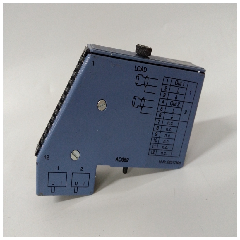
B&R 7AO352.70旋入式模块,7AO352.70使用手册
初始条件在您验证所有必要的硬件准备已完成后已完成,所有连接均已正确完成,并且安装完成后,您可以启动系统。将功率应用于系统(以及重置系统)触发MVME172LX的MPU、硬件和固件以及系统闪存驻留固件初始化MVME172LX上的设备为启动操作系统做准备。固件为出厂时附带一组适当的默认值。在大多数情况下在启动之前,无需修改固件配置操作系统。有关这方面的详细信息,请参阅第3章和MVME172Bug固件的用户文档。


B&R 7AO352.70旋入式模块施加功率2当系统通电(或重置)时,固件将执行一些自检并继续进行硬件初始化。系统启动流程按预定顺序进行,遵循层次结构处理器和MVME172LX硬件固有。数字下图显示了发生的基本初始化序列的流程在系统启动期间。启动前检查表在给MVME172LX系统通电之前,请确保:存在条件:MVME172LX VME上的跳线和/或配置开关根据需要设置嵌入式控制器和相关设备适用于您的特定应用。2.MVME172LX板的安装和电缆连接视情况而定适用于您的特定机箱或系统,如第1章所述。3、您计划用作系统控制台的终端已连接至MVME172LX模块上的控制台端口(串行端口1)。4、终端设置如下:–每个字符8位–每个字符一个停止位奇偶校验禁用(无奇偶校验保护)–波特率9600波特(许多串行端口的默认波特率通电时)5、您希望使用的任何其他设备,如主机系统和/或外围设备连接到适当的连接器。完成上面列出的检查后,您可以为系统
Initial Conditions
After you have verified that all necessary hardware preparation has been
done, that all connections have been made correctly, and that the
installation is complete, you can power up the system. Applying power to
the system (as well as resetting it) triggers an initialization of the
MVME172LX’s MPU, hardware, and firmware along with the rest of the
system.
The Flash-resident firmware initializes the devices on the MVME172LX
board in preparation for booting the operating system. The firmware is
shipped from the factory with an appropriate set of defaults. In most cases
there is no need to modify the firmware configuration before you boot the
operating system. For specifics in this regard, refer to Chapter 3 and to the
user documentation for the MVME172Bug firmware.Applying Power 2
When you power up (or when you reset) the system, the firmware executes
some self-checks and proceeds to the hardware initialization. The system
startup flows in a predetermined sequence, following the hierarchy
inherent in the processor and the MVME172LX hardware. The figure
below charts the flow of the basic initialization sequence that takes place
during system startup.Pre-Startup Checklist
Before you power up the MVME172LX system, be sure that the following
conditions exist:
1. Jumpers and/or configuration switches on the MVME172LX VME
Embedded Controller and associated equipment are set as required
for your particular application.
2. The MVME172LX board is installed and cabled up as appropriate
for your particular chassis or system, as outlined in Chapter 1.
3. The terminal that you plan to use as the system console is connected
to the console port (serial port 1) on the MVME172LX module.
4. The terminal is set up as follows:
– Eight bits per character
– One stop bit per character
– Parity disabled (no parity protection)
– Baud rate 9600 baud (the default baud rate of many serial ports
at power-up)
5. Any other device that you wish to use, such as a host computer
system and/or peripheral equipment, is cabled to the appropriate
connectors.
After you complete the checks listed above, you are ready to power up the
system.


