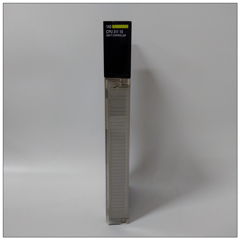
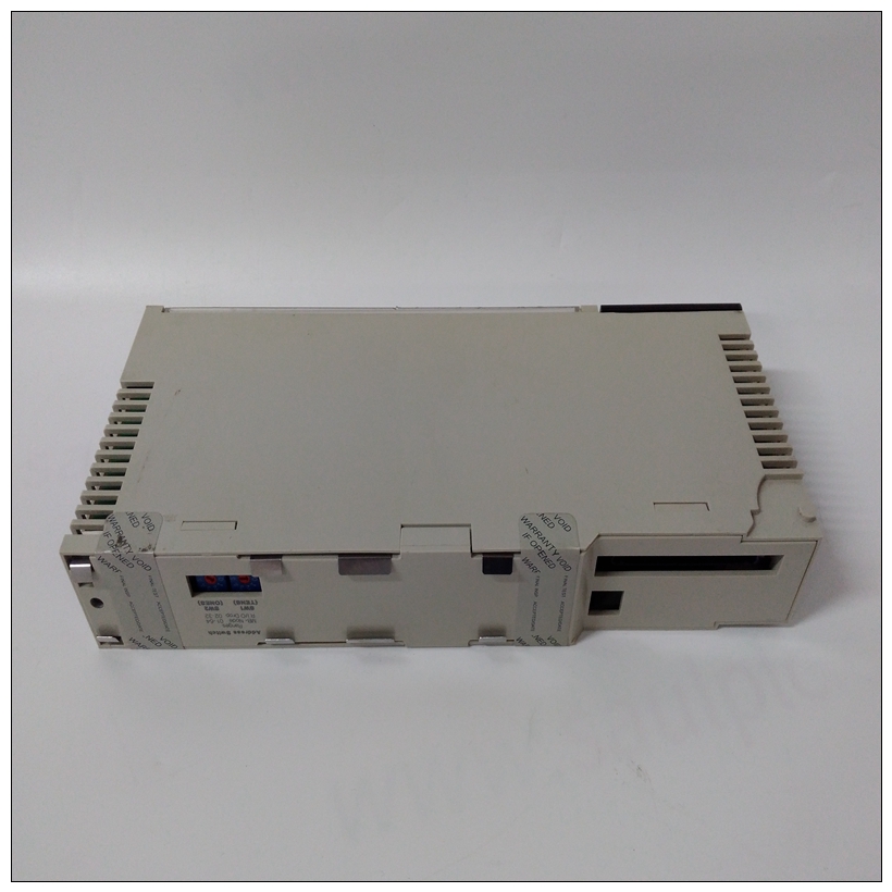
140CPU31110处理器模块,SCHNEIDER参数说明
看门狗定时器PCC包括看门狗定时器功能。当由启用时软件,看门狗定时器可编程为重置
模块(如果是系统控制器)。每当看门狗定时器超时时,故障指示灯点亮(除了BRDFAIL位在VMEchip中设置)。看门狗定时器对滴答定时器1的输出进行计数。如果看门狗定时器不会由编程内的软件重置滴答声的数量,它超时。


140CPU31110处理器模块打印机接口PCC具有与Centronics兼容的打印机接口。打印机当MC68030准备好接收数据或出现故障。中断级别可编程,并提供请求时的状态/ID向量。控制和状态寄存器PCC具有输入和输出信号线,用于控制各种MVME147上的功能。DRAM有控制线奇偶校验启用、奇偶校验测试和奇偶校验错误状态、VMEbus映射选择、多地址RMC模式和LANCE地址选择。重置和中止开关PCC提供重置和中止开关接口。复位开关信号被解除抖动,当其启用时,它将导致复位输出信号。复位开关可以启用/禁用通过软件。
中止开关信号被解除抖动并发送到7级断续器。启用时,中止开关导致7级中断至MC68030。中断器返回状态/ID请求时的矢量。可以启用/禁用中止开关通过软件。通电复位当PCC接收到通电复位信号时,它会生成一个复位信号输出信号并在控制寄存器中设置通电位。这个
通电位可由软件用于确定何时发生通电重置。
Watchdog Timer
The PCC includes a watchdog timer function. When enabled by
software, the watchdog timer may be programmed to reset the
module if it is system controller. Whenever the watchdog timer
times out, the FAIL LED is lit (in addition to when the BRDFAIL bit
is set in the VMEchip).
The watchdog timer counts outputs from tick timer 1. If the
watchdog timer is not reset by software within the programmed
number of ticks, it times out. Printer Interface
The PCC has a Centronics compatible printer interface. The printer
interface interrupts the MC68030 when it is ready for data or when
a fault occurs. The interrupt level is programmable and it provides
a status/ID vector when requested.
Control and Status Registers
The PCC has input and output signal lines for controlling various
functions on the MVME147. There are control lines for DRAM
parity enable, parity test and parity error status, VMEbus map
select, multiple address RMC mode, and LANCE address select.
RESET and ABORT Switches
The PCC provides the RESET and ABORT switch interface.
The RESET switch signal is debounced and when it is enabled, it
causes a reset out signal. The RESET switch can be enabled/disabled
by software.
The ABORT switch signal is debounced and sent to the level 7
interrupter. When it is enabled, the ABORT switch causes a level 7
interrupt to the MC68030. The interrupter returns a status/ID
vector when requested. The ABORT switch can be enabled/disabled
by software.
Power-Up Reset
When the PCC receives a power-up reset signal, it generates a reset
out signal and sets the power-up bit in the control register. The
power-up bit can be used by software to determine when a powerup reset has occurred.


