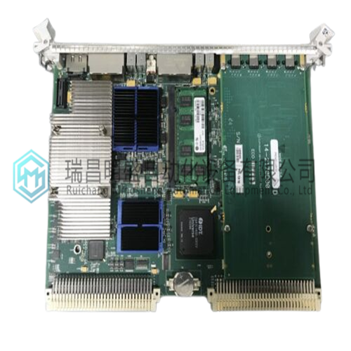
GE 605-109114-004数字输入模块
1.产 品 资 料 介 绍:
中文资料:
以下过程概述了GE 605-109114-004在VMEbus机箱中的安装以及网络环形拓扑的设置。GE 605-109114-004可以安装在任何插槽中,但插槽1除外,插槽1通常是为系统控制器保留的。1.在机箱中安装板之前,确保所有开关都设置为所需的操作模式。请参阅第36页的开关/跳线配置和位置。2.在电源关闭的情况下,将GE 605-109114-004安装到机箱中,确保板连接器与背板连接器牢固配合。
3.使用位于前面板顶部和底部的两个螺钉将GE 605-109114-004固定到机箱。4.将光纤电缆连接到TX和RX连接器。5.将连接到TX的光纤电缆布线到环中下一个板的RX连接器。将光纤电缆从该板的TX连接到下一个板的RX连接器。重复此步骤,直到环中的最后一个节点将其TX路由到第一个节点的RX。有关六节点环的示例,请参阅第47页的图2-9。
英文资料:
The following procedure outlines the installation of the GE 605-109114-004 in a VMEbus chassis and the set-up of the network ring topology. The GE 605-109114-004 can be installed in any slot with the exception of slot one, which normally is reserved for the system controller. 1. Before installation of the board in the chassis, ensure that all switches are set for the desired mode of operation. Refer to Switch/Jumper Configuration and Location on page 36. 2. With the power turned OFF, install the GE 605-109114-004 into the chassis, making sure that the board connectors are firmly mated to the backplane connectors.
3. Secure the GE 605-109114-004 to the chassis using the two screws located at the top and bottom of the front panel. 4. Connect the fiber-optic cables to the TX and RX connectors. 5. Route the fiber-optic cable connected to TX to the RX connector of the next board in the ring. Connect the fiber-optic cable from that board’s TX to the RX connector of the next board. Repeat this step until the last node in the ring routes its TX to the RX of the first node. Refer to Figure 2-9 on page 47 for an example of a six node ring.
2.产 品 展 示

3.主 营 品 牌

本篇文章出自瑞昌明盛自动化设备有限公司官网,转载请附上此链接:http://www.jiangxidcs.com


