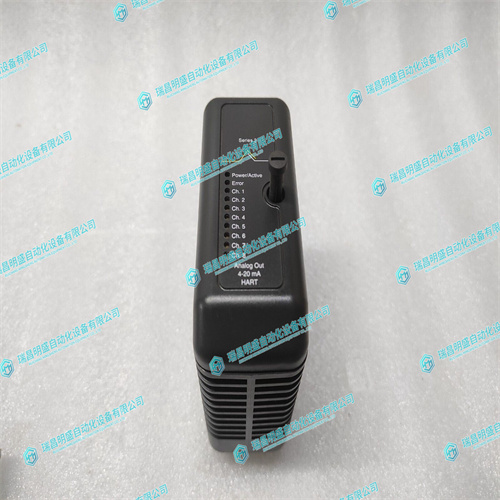
EMERSON KJ3221X1-BA1模拟输入模块
启用出站窗口7(OTAT7),SST320处的2eSST定时,SCT传输模式,CR/CSR监控访问。该窗口接受PCI-X本地总线上0xB1000000-0xB1FF0000的传输,并使用0x4F000000的偏移量将其转换到VMEbus上,因此,PCI-X本地母线上的0xB1000000访问变为VMEbus的0x00000000访问。6.5.2控制寄存器/控制状态寄存器设置CR/CSR基地址根据地理地址初始化为适当的设置;即VME时隙号。有关详细信息,请参阅VME64规范和VME64扩展。因此,可以使用CR/CSR AM代码从VMEbus访问512 KB的CR/CSR区域。6.5.3显示VME设置要显示可更改的VME设置,请在固件提示下键入以下内容:要显示主启用状态:vmeCfg–s–m要显示选定的入站窗口状态:vmeCfg–s-i(0-7)要显示选定出站窗口状态,请键入以下内容
Outbound window 7 (OTAT7) is enabled, 2eSST timing at SST320, transfer mode of SCT,
CR/CSR Supervisory access. The window accepts transfers on the PCI-X Local Bus from
0xB1000000-0xB1FF0000 and translates them onto the VMEbus using an offset of
0x4F000000, thus an access to 0xB1000000 on the PCI-X Local Bus becomes an access
to 0x00000000 on the VMEbus.
6.5.2 Control Register/Control Status Register Settings
The CR/CSR base address is initialized to the appropriate setting based on the
Geographical address; that is, the VME slot number. See the VME64 Specification and the
VME64 Extensions for details. As a result, a 512 KB CR/CSR area can be accessed from
the VMEbus using the CR/CSR AM code.
6.5.3 Displaying VME Settings
To display the changeable VME setting, type the following at the firmware prompt:
To display Master Enable state:
vmeCfg –s –m
To display selected Inbound Window state:
vmeCfg –s –i(0 - 7)
To display selected Outbound Window state:
vmeCfg –s –o(0 - 7)


