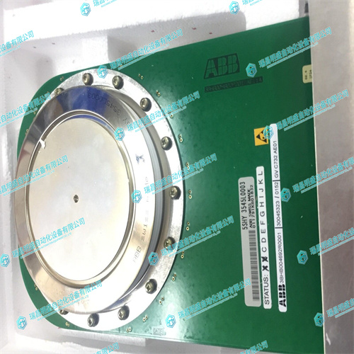
ABB 5SHY3545L0003 336A4954ARP1可控硅高压变频
从电源管理基础I/O地址读取偏移31h的字节用于获得这些位。位5、6和7分别对应于定时器2、1和0,图4-2定时器中断状态寄存器为了清除定时器中断状态,首先将零(0)写入位于电源管理基础I/O地址位3、4和6的偏移37h处的通用输出寄存器(不是位3、3和5)。然后将1写入这些相同的位,以重新启用定时器中断状态寄存器。位3、4和6分别对应于定时器2、1和0,用于清除中断。使用用于清除PC/AT IRQ5的标准程序清除定时器中断。定时器编程体系结构VMIVME-7740定时器映射在I/O地址空间中,从$500开始(见表4-1)。计时器由三个16位计时器和一个控制字寄存器(见图4-4)组成,通过8位数据总线进行读/写。
A byte read of Offset 31h from the Power Management Base I/O address is used to obtain these bits. Bits 5, 6, and 7 correspond to Timers 2, 1, and 0, respectively Figure 4-2 Timer Interrupt Status Register In order to clear the Timer Interrupt Status register, first write zeros (0’s) to the general-purpose output register located at offset 37h of the Power Management Base I/O address Bits 3, 4, and 6 (Not Bits 3, 4 and 5). Then write ones (1’s) to these same bits to re-enable the Timer Interrupt Status register. Bits 3, 4, and 6 correspond to Timers 2, 1, and 0, respectively Clearing the Interrupt The Timer Interrupts are cleared using the standard procedure for clearing PC/AT IRQ5. Timer Programming Architecture The VMIVME-7740 Timers are mapped in I/O address space starting at $500 (see Table 4-1). The Timers, consisting of three 16-bit timers and a Control Word Register (see Figure 4-4) are read from/written to via an 8-bit data bus.


