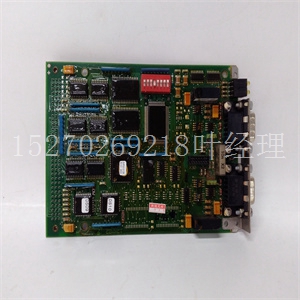
GFD563A101 3BHE046836R0101卡件
一个安全的地方供以后使用。表2-3。串行接口模块零件号EIA标准配置零件号型号EIA-232-D DTE 01-W3846B SIMM05 DCE 01-W3865B SIMM06 EIA-530 DTE 01-W3868B SIMM07 DCE 01-W867B SIMM08 EIA-485--01-W3002F SIMM09或EIA-422 DTE或DCE SECONDARY SIDE 39 1 40 2 J1 1568 9502 2-8计算机组文献中心网站硬件准备和安装2 2。抓住SIMM的相对两侧,轻轻地将其向上提起!注意:为防止损坏SIMM或主板上的连接器,请避免仅从一侧提起SIMM。3.将SIMM放在受保护(无静电)的容器中,以备再次使用。安装新SIMM 1。观察SIMM接头J1和控制器接头J10上接头键的方向。转动SIMM,使键对齐,并将其轻轻地放在连接器J10上,使SIMM角(或中心)处的安装孔与控制器上的匹配支座对齐。2.轻轻按压SIMM的顶部,使其位于连接器上。如果SIMM没有轻轻按压,则重新检查方向。如果SIMM连接器方向不正确,安装孔将不会与支座对齐!注意:为防止损坏SIMM,如果方向不正确,请勿强行打开SIMM。3.将一个或两个(根据需要)4-40 x 3/16“十字头螺钉(之前已拆除或随新SIMM一起提供)插入中心或对角安装孔。将螺钉安装到支座中,但不要过度拧紧。图2-3、2-4、2-5和2-6说明了端口A和B可用的各种串行配置中的信号关系和信号连接。系统控制器选择收割台(J1)http://www.mcg.mot.com/literature2-9串行端口1/控制台的2个同步时钟选择标头(J11)MVME162FX嵌入式控制器出厂时带有配置用于异步通信的串行端口1/Console标头(已移除跳线)。要选择串行端口1/控制台连接的同步通信,请在引脚1和2以及引脚3和4之间安装跳线。串行端口2的时钟选择标头(J12)MVME162FX嵌入式控制器出厂时已配置串行端口2标头用于异步通信(即,已移除跳线)。要选择串行端口2连接的同步通信,请在引脚1和2以及引脚3和4之间安装跳线。如果将MVME712M与控制器一起使用,请如上所示配置MVME712 M。有关更多信息,请参阅第1章中的MVME712章节。J11 J11内部时钟(出厂配置)外部时钟2 4 4 2 1 3 1 2-10计算机组文献中心网站硬件准备2硬件准备2 SRAM电池备用电源选择标题(J20)MVME162FX嵌入式控制器出厂配置为使用VMEbus+5V备用电源作为SRAM的备用电源(跳线安装在引脚1和3以及2和4之间)。要选择车载电池作为备用电源,请在针脚3和5以及针脚4和6之间安装跳线。注意:对于没有可选VMEbus接口(没有VMEchip2 ASIC)的MVME162FXs,您必须选择板载电池作为备用电源!注意:移除所有跳线可能会暂时禁用控制器的SRAM。不要从J20上拆下所有跳线,除非存放。J12 J12内部时钟(出厂配置)外部时钟2 4 4 2 1 3 1系统控制器选择标题(J1)http://www.mcg.mot.com/literature2-11 2 EPROM大小选择头(J21)MVME162FX嵌入式控制器在工厂配置为4位EPROM(跨接脚2和3安装跳线)。要为8Mbit EPROM配置MVME162FX,请在引脚1和2之间安装跳线。通用可读跳线头(J22)头J22提供八个可读跳线。这些跳线作为寄存器($FFF4202D)读取
a safe place for later use. Table 2-3. Serial Interface Module Part Numbers EIA Standard Configuration Part Number Model Number EIA-232-D DTE 01-W3846B SIMM05 DCE 01-W3865B SIMM06 EIA-530 DTE 01-W3868B SIMM07 DCE 01-W3867B SIMM08 EIA-485 -- 01-W3002F SIMM09 or EIA-422 DTE or DCE SECONDARY SIDE 39 1 40 2 J1 1568 9502 2-8 Computer Group Literature Center Web Site Hardware Preparation and Installation 2 2. Grasp the opposite sides of the SIMM and gently lift it straight up. ! Caution To prevent damage to the connector on the SIMM or the main board, avoid lifting the SIMM by one side only. 3. Place the SIMM in a protected (static-free) container for possible reuse. Installation of New SIMM 1. Observe the orientation of the connector keys on the SIMM connector J1 and on the controller connector J10. Turn the SIMM so that the keys are lined up and place it gently on connector J10, aligning the mounting hole(s) at the SIMM corners (or center) with the matching standoff(s) on the controller. 2. Gently press the top of the SIMM to seat it on the connector. If the SIMM does not seat with gentle pressure, recheck the orientation. If the SIMM connector is oriented incorrectly, the mounting hole(s) will not line up with the standoff(s). ! Caution To prevent damage to the SIMM, do not force the SIMM on if it is oriented incorrectly. 3. Insert one or two (as required) 4-40 x 3 /16” phillips-head screw(s) (that were previously removed or supplied with the new SIMM) into the center or opposite corner mounting hole(s). Install the screw(s) into the standoff(s), but do not overtighten. The signal relationships and signal connections in the various serial configurations available for ports A and B are illustrated in Figures 2-3, 2- 4, 2-5, and 2-6. System Controller Select Header (J1) http://www.mcg.mot.com/literature 2-9 2 Synchronous Clock Select Header (J11) for Serial Port 1/Console The MVME162FX Embedded Controller is shipped from the factory with the SERIAL PORT 1/CONSOLE header configured for asynchronous communications (jumpers removed). To select synchronous communications for the SERIAL PORT 1/CONSOLE connection, install jumpers across pins 1 and 2 and pins 3 and 4. Clock Select Header (J12) for Serial Port 2 The MVME162FX Embedded Controller is shipped from the factory with the SERIAL PORT 2 header configured for asynchronous communications (i.e., jumpers removed). To select synchronous communications for the SERIAL PORT 2 connection, install jumpers across pins 1 and 2 and pins 3 and 4. If you are using a MVME712M with the controller, configure the MVME712M as shown above. Refer to the MVME712 section in Chapter 1 for additional information. J11 J11 Internal Clock (factory configuration) External Clock 2 4 4 2 1 3 3 1 2-10 Computer Group Literature Center Web Site Hardware Preparation 2 2Hardware Preparation SRAM Battery Backup Source Select Header (J20) The MVME162FX Embedded Controller is factory configured to use VMEbus +5V standby power as a backup power source for the SRAM (jumpers are installed across pins 1 and 3 and 2 and 4). To select the onboard battery as the backup power source, install the jumpers across pins 3 and 5 and 4 and 6. Note For MVME162FXs without optional VMEbus interface (without VMEchip2 ASIC), you must select the onboard battery for the backup power source. ! Caution Removing all jumpers may temporarily disable the controller’s SRAM. Do not remove all jumpers from J20, except for storage. J12 J12 Internal Clock (factory configuration) External Clock 2 4 4 2 1 3 3 1 System Controller Select Header (J1) http://www.mcg.mot.com/literature 2-11 2 EPROM Size Select Header (J21) The MVME162FX Embedded Controller is factory-configured for a 4Mbit EPROM (a jumper is installed across pins 2 and 3). To configure the MVME162FX for an 8Mbit EPROM, install the jumper across pins 1 and 2. General Purpose Readable Jumpers Header (J22) Header J22 provides eight readable jumpers. These jumpers are read as a register (at $FFF4202D) in the


