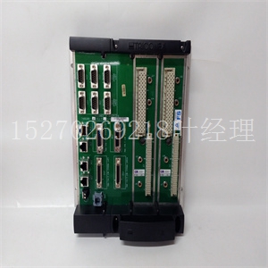
GFD563A102 3BHE046836R0102工业卡件,ABB卡件
包含特定任务的编号。开始之前,请务必阅读本章的全部内容,包括所有注意事项和警告注释。表2-1。启动概述为了…请参阅…第页。。。打开硬件包装。开箱说明2-2通过在控制器和转换模块上设置跳线来准备硬件。MVME162FX硬件准备和MVME712过渡模块准备2-2和1-20在控制器上安装Industry Pack(IP)模块。MVME162FX 2-17上的IP安装在机箱中安装控制器。MVME162FX模块安装2-18 2-2计算机组文献中心网站硬件准备和安装2开箱说明!注意:为防止静电放电损坏控制器,请避免触摸电路板的表面和部件。静电放电会损坏集成电路和其他静电敏感元件。注意:如果装运纸箱在收到时损坏,请在开箱和检查设备时要求承运人的代理人在场。将设备从装运纸箱中取出。参考装箱单,确认所有项目都存在。保存包装材料,以便储存和重新装运设备。将设备放置在清洁且充分保护的工作表面上。连接控制台端子。系统注意事项,MVME162FX VMEmodule 2-20连接您将使用的任何其他设备。MVME162FX连接,MVME712M注:有关可选装置和设备的更多信息,请参阅随设备提供的文档。2-23给系统通电。使用MVME162FX模块操作162Bug。安装和启动3-4熟悉调试器命令。使用调试器4-1根据应用程序的需要对电路板进行编程。CNFG和ENV命令5-1表2-1。启动概述(续)为了…请参阅…第页。。。硬件准备http://www.mcg.mot.com/literature2-3硬件准备2为确保MVME162FX嵌入式控制器正常运行,安装前可能需要对某些选项进行修改。控制器为大多数这些选项提供软件控制。在控制器安装在系统中之后,通过在控制寄存器中设置位来执行修改。有关MVME162FX寄存器的更多信息,请参阅附录F中列出的《MVME162FXEmbedded Controller编程器参考指南》。注意,某些选项无法在软件中设置;可通过安装或移除接头跳线或接口模块对其进行修改。图2-1显示了控制器上开关、跳线头、连接器和LED的位置。控制器已进行出厂测试,出厂时带有以下章节所述的默认出厂跳线设置。控制器使用所需的工厂安装调试监视器MVME162Bug(162Bug)以及这些工厂跳线设置进行操作。下表列出了可手动配置的项目。表2-2。跳线可配置选项选项出厂默认系统控制器选择(J1)1-2串行端口B配置的SIMM选择(J10)SIMM06串行端口1/控制台的同步时钟选择(J11)无跳线串行端口2的同步时钟选项(J12)无跳线SRAM备用电源选择(J20)1-3,2-4 EPROM大小选择(J21)2-3通用可读寄存器配置(J22)1-2、3-4、5-6、7-8、9-10、11-
number(s) that contain the specific task. Be sure to read this entire chapter, including all CAUTION and WARNING notes, before you begin. Table 2-1. Startup Overview In order to... Refer to... On page... Unpack the hardware. Unpacking Instructions 2-2 Prepare the hardware by setting jumpers on the controller and transition modules. MVME162FX Hardware Preparation and MVME712 Transition Module Preparation 2-2 and 1-20 Install the Industry Pack (IP) modules on the controller. IP Installation on the MVME162FX 2-17 Install the controller in the chassis. MVME162FX Module Installation 2-18 2-2 Computer Group Literature Center Web Site Hardware Preparation and Installation 2 Unpacking Instructions ! Caution To prevent static discharge damage to the controller, avoid touching the surface and components of the circuit board. Static discharge can damage integrated circuits and other static sensitive components. Note If the shipping carton is damaged upon receipt, request the carrier’s agent to be present during unpacking and inspection of equipment. Unpack the equipment from the shipping carton. Refer to the packing list and verify that all items are present. Save the packing material for storing and reshipping the equipment. Place the equipment on a clean and adequately protected working surface. Connect a console terminal. System Considerations, MVME162FX VMEmodule 2-20 Connect any other equipment you will be using. MVME162FX Connections, MVME712M NOTE: For additional information on optional devices and equipment, refer to the documentation provided with the equipment. 2-23 Power up the system. Operate 162Bug with the MVME162FX module. Installation and Startup 3-4 Familiarize yourself with Debugger commands. Using the Debugger 4-1 Program the board as needed for your applications. CNFG and ENV commands 5-1 Table 2-1. Startup Overview (Continued) In order to... Refer to... On page... Hardware Preparation http://www.mcg.mot.com/literature 2-3 Hardware Preparation 2 To ensure proper operation of the MVME162FX Embedded Controller, modifications to certain options may be necessary before installation. The controller provides software control for most of these options. Modifications are performed by setting bits in control registers after the controller has been installed in a system. For additional information on MVME162FX registers, refer to the MVME162FX Embedded Controller Programmer’s Reference Guide listed in Appendix F. Note that Some options cannot be set in the software; these are modified by installing or removing header jumpers or interface modules. Figure 2-1 shows the locations of the switches, jumper headers, connectors, and LEDs on the controller. The controller has been factory tested and is shipped with the default factory jumper settings described in the following sections. The controller operates with its required and factory-installed debug monitor, MVME162Bug (162Bug), with these factory jumper settings. Manually configurable items are listed in the following table. Table 2-2. Jumper-Configurable Options Option Factory Default System controller selection (J1) 1-2 SIMM selection for serial port B configuration (J10) SIMM06 Synchronous clock selection for Serial Port 1/Console (J11) No jumper Synchronous clock selection for Serial Port 2 (J12) No jumper SRAM backup power source selection (J20) 1-3, 2-4 EPROM size selection (J21) 2-3 General-purpose readable register configuration (J22) 1-2, 3-4, 5-6, 7-8, 9-10, 11-


