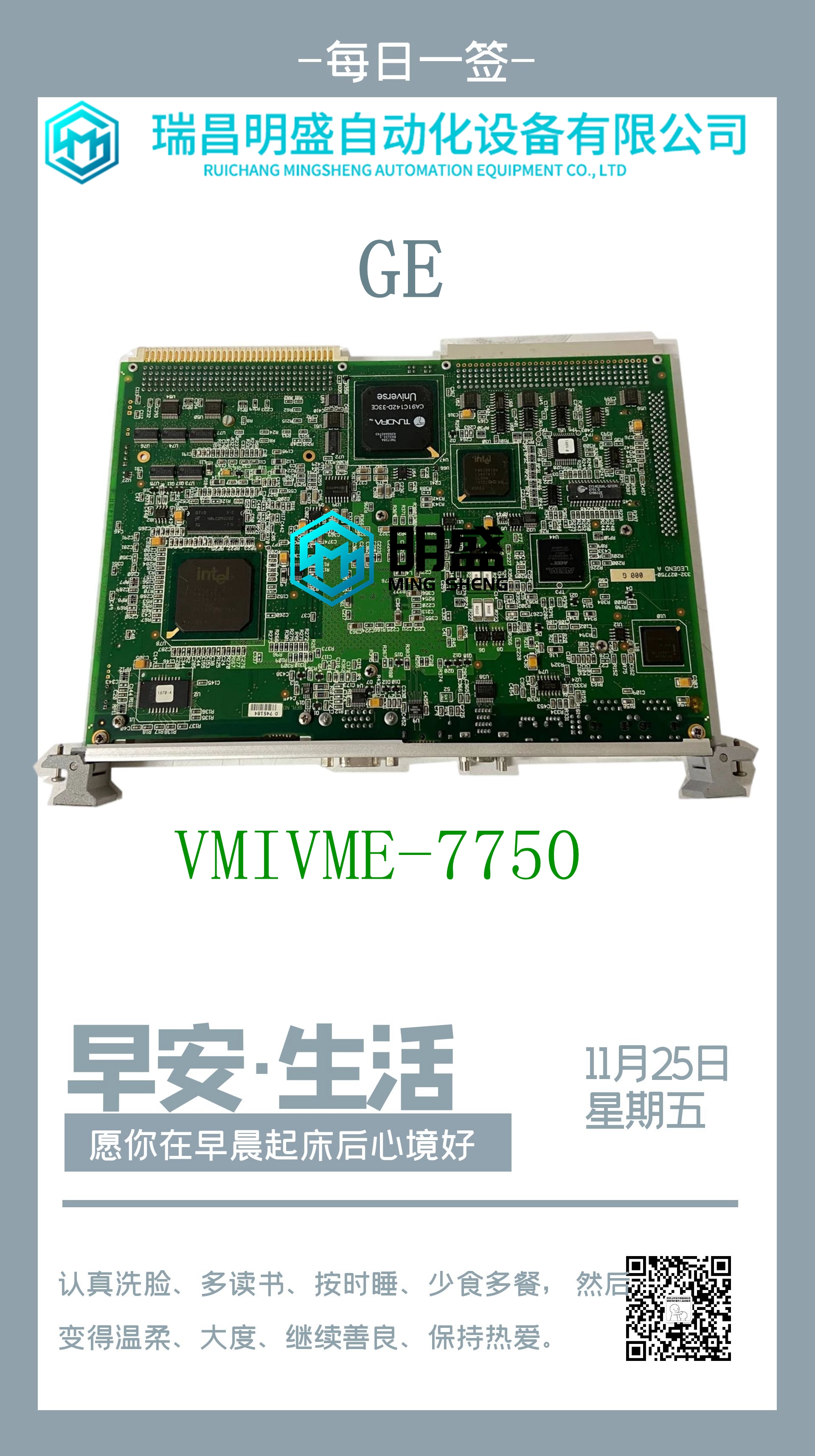
HIEE-200038-R1 UU-A333-BE01机器人模块卡件
网络数据速度(10或100Mbps)。当LED状态为ON时,该网络端口的网络连接为100 Mbps。链路–LED指示网络链路状态和活动。当LED状态为ON时,链路已物理连接。当LED闪烁时,在该网络端口处检测到流量。(端口处的流量不表示以太网接口处存在流量。流量可能会在交换机的端口之间引入。)IC695ETM001 Kxxx接口模块的正面有六个单色绿色LED。两个以太网端口的LED分别标记为10、100、1000。两个以太网端口(1和2)位于接口模块的下侧。当LED状态为ON时,链路已物理连接。当LED闪烁时,在该网络端口检测到流量。LED标签指示网络流量速度。PAC系统™ RX3i和RSTi EP TCP/IP以太网通信用户手册第3节GFK-2224Y 2019年8月安装和启动:以太网模块接口32.3.1.5重启/重置按钮操作对于PACSystems以太网接口,当按下并释放重启/重置按键时,将发生以太网重启。按下重启/复位按钮的持续时间决定了重启发生后的操作。如果以太网接口使用任何可选的以太网插件应用程序,这些应用程序通常在每次通电或重新启动时启动。要在不启动任何以太网插件应用程序的情况下重新启动以太网接口,请按住以太网重新启动/重置按钮5到10秒。如果以太网接口能够重新启动固件更新操作,则按住以太网重新启动按钮10秒以上。这通常在故障排除期间完成,以绕过可能无效的固件,并允许使用WinLoader加载有效的固件。如果以太网接口使用重置按钮设置固定的临时IP地址,请按住重置按钮五秒钟以上。进入IP设置模式将在前面板的交通速度LED上显示灯模式。下面列出了按钮控制的重启操作,每个操作都有LED指示:重启操作ETM001 Jx–按住重启功能ETM001 Kxxx–按住重置功能正常重启以太网接口,并启动正在使用的任何可选以太网插件应用程序。少于五秒少于五秒重新启动以太网接口,而不启动任何以太网插件应用程序。5到10秒N/A进入IP设置模式以设置初始IP地址。N/A超过5秒重新启动以太网接口,进入固件更新操作。重新启动后超过10秒,在通电时按住重置按钮(直到前三个LED闪烁)当强制进入固件更新操作时,但在固件更新开始之前,再次按下以太网重新启动/重置按钮以退出固件更新模式并使用现有固件重新启动。固件更新开始后,将擦除现有固件,并禁用以太网重启/重置按钮,直到固件更新完成。如果错误进入固件更新模式,只需从背板上卸下并更换以太网模块。用重置按钮设置临时IP地址要使用重置按钮设置一个临时IP地址,请参阅使用重置按钮分配临时IP地址一节。PAC系统™ RX3i和RSTi EP TCP/IP以太网通信用户手册第3节GFK-2224Y 2019年8月安装和启动:以太网模块接口33 PACSystems™ RX3i和RSTi EP TCP/IP以太网通信用户手册第3节GFK-2224Y 2019年8月安装和启动:以太网模块接口34 3.2以太网模块安装有关模块和系统安装的一般信息,或如果安装要求符合CE标志,请参阅PACSystems RX3i系统手册GFK-2314。3.2.1模块安装1。牢牢握住模块,将模块与正确的插槽和连接器对齐。图9:将模块安装到RX3i背板2中。将模块的后枢轴钩接合在背板(1)顶部的槽口中。3.向下摆动模块(2),直到模块的连接器与背板的背板连接器接合。4.ETM001 Kxxx:使用模块附带的机器螺钉(3)将模块底部固定到背板上。ETM001:用弹簧锁闩机构固定底部。3.2.2模块拆卸1。ETM001 Jx和ETM001 Kxxx可在向机架供电的情况下从RX3i机架上卸下。图10:从RX3i背板2上卸下模块。ETM001 Kxxx:松开模块(1)底部的螺钉。ETM001:释放弹簧式闩锁机构
network data speed (10 or 100 Mbps). When the LED state is ON, the network connection at that network port is 100 Mbps. Link – LED indicates network link status and activity. When the LED state is ON, the link is physically connected. When the LED blinks, traffic is detected at that network port. (Traffic at the port does not indicate traffic is present at the Ethernet interface. Traffic may be introduced between ports of the switch.) IC695ETM001-Kxxx Six single color green LEDs are located on the face of the interface module. The LEDs are labeled 10, 100, 1000 for each of the two Ethernet ports. Two Ethernet ports (1 and2) are located on the underside of the interface module. When the LED state is ON, the link is physically connected. When the LED blinks, traffic is detected at that network port. The LED label indicates the network traffic speed. PACSystems™ RX3i and RSTi-EP TCP/IP Ethernet Communications User Manual Section 3 GFK-2224Y August 2019 Installation and Start-up: Ethernet Module Interfaces 32 3.1.5 Restart/Reset Pushbutton Operation For PACSystems Ethernet interfaces, an Ethernet restart occurs when the restart/reset pushbutton is pressed and released. The duration that the restart/reset pushbutton is pressed determines the operation after the restart occurs. If the Ethernet interface uses any optional Ethernet plug-in applications, these applications are ordinarily started upon each power-up or restart. To restart the Ethernet interface without starting any Ethernet plug-in applications, press and hold the Ethernet restart/reset pushbutton between five and 10 seconds. If the Ethernet interface is able to restart into firmware update operation, press and hold the Ethernet restart pushbutton for more than 10 seconds. This is typically done during troubleshooting to bypass possibly invalid firmware and allow valid firmware to be loaded using WinLoader. If the Ethernet interface uses the reset button to set a fixed temporary IP address, press and hold the reset button for more than five seconds. Entering the IP Setup Mode will display a light pattern on the front panel’s traffic speed LEDs. Pushbutton-controlled restart operations are listed below, with the LED indications for each: Restart Operation ETM001-Jx – Press and Hold Restart Functionality ETM001-Kxxx - Press and Hold Reset Functionality Restart the Ethernet interface normally, and start any optional Ethernet plug-in applications that are being used. Less than five seconds Less than five seconds Restart the Ethernet interface without starting any Ethernet plug-in applications. Five to 10 seconds N/A Put into IP Setup Mode to set initial IP address. N/A More than five seconds Restart the Ethernet interface into firmware update operation. More than 10 seconds After restart, press and hold reset button on power up (until the top three LEDs flash) When forced into firmware update operation, but before the firmware update begins, press the Ethernet Restart/Reset pushbutton again to exit the firmware update mode and restart with the existing firmware. Once the firmware update begins, the existing firmware is erased and the Ethernet Restart/Reset pushbutton is disabled until the firmware update is complete. If the firmware update mode was entered mistakenly, simply remove and replace the Ethernet module from the backplane. Setting a Temporary IP Address with the Reset Button To use the Reset Button to set a temporary IP address, refer to section Assigning a Temporary IP Address Using the Reset Button. PACSystems™ RX3i and RSTi-EP TCP/IP Ethernet Communications User Manual Section 3 GFK-2224Y August 2019 Installation and Start-up: Ethernet Module Interfaces 33 PACSystems™ RX3i and RSTi-EP TCP/IP Ethernet Communications User Manual Section 3 GFK-2224Y August 2019 Installation and Start-up: Ethernet Module Interfaces 34 3.2 Ethernet Module Installation For general information about module and system installation, or if the installation requires CE Mark compliance, refer to the PACSystems RX3i System Manual, GFK-2314. 3.2.1 Module Installation 1. Holding the module firmly, align the module with the correct slot and connector. Figure 9: Install Module into RX3i Backplane 2. Engage the module’s rear pivot hook in the notch on the top of the backplane (1). 3. Swing the module down (2) until the module’s connector engages the backplane’s backplane connector. 4. ETM001-Kxxx: Secure the bottom of the module to the backplane using the machine screws provided with the module (3). ETM001: Secure bottom with spring-loaded latch mechanism. 3.2.2 Module Removal 1. The ETM001-Jx and ETM001-Kxxx may be removed from the RX3i rack with the power supplied to the rack. Figure 10: Remove Module from RX3i Backplane 2. ETM001-Kxxx: Loosen the screws at the bottom of the module (1). ETM001: Release the spring-loaded latch mechanism


