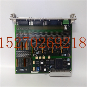
HIEE300025R2系统模块卡件
并且通道1 LED点亮)。继电器在接通和断开状态之间连续交替。4.信道2错误(如果电源和状态指示灯点亮,信道2指示灯点亮)。继电器在接通和断开状态之间连续交替。5.风扇故障–风扇工作不正常。继电器处于断开状态。b、 第3章详细介绍了LED指示。见表3.1(主模块)和表3.2(从模块)。图2.4–外部故障连接器公共信号(C)外部故障连接器常闭信号(NC)C NC常开常开信号(NO)第13页1998年11月20日第2章:安装配置。2.3.3 DB37连接器DB37连接器用于将光纤扩展接口模块连接至HE697BEM713发射器或IC697BEM711接收器。光纤主单元通过37路M/F电缆(部件号:接口连接器)直接连接到HE697BEM713总线变送器。主单元HE697FBX105有四个光纤连接器,而从单元(HE697FBX100)只有两个。每个光纤通道都有一对光纤连接器。因此,主单元有两个光纤通道,从单元只有一个光纤通道。2.5信道选择开关一个双向双列直插式开关用于打开/关闭主设备中的每个信道,位于印刷电路板盖的下方。从属单元中不存在开关。开关的设置1对应于通道1,设置2对应于通道2。要激活通道,必须将相应的开关设置移至ON(接通)位置。要关闭频道,请将开关设置从ON位置移开。默认情况下,两个开关设置都处于ON位置。2.6提供的零件HE697FBX105和HE697FBX100模块包含以下零件。重要的是将所提供的部件与主模块和从模块一起使用,以满足CE标准,并确保正常工作。a.电源线(9针)500A0015(见图2.8)b.电源线滤波器c.调制解调器滤波器CH2 CH1 CH2 CH2 RX TX TX RX图2.6–光纤连接图2.7–第15页2路双列直插式开关1 2 1998年11月20日CH.2:安装。/配置。图2.8–电源电缆(配备HE697FBX105和100模块)2 1 3 4屏蔽2对双绞线,带箔屏蔽和排水线9针外螺纹DB PHOENIX 2位置连接器红色黑色引脚1红色黑色使用提供的电缆夹和夹屏蔽在此处良好接地。CH.3:操作1998年11月20日第16页第3章:操作3.1光纤扩展接口操作(见图3.1和3.2)3.1.1概述Horner电子发射器(HE697BEM713)通过光纤扩展接口主模块(HE697FBX105)和从模块(HE97FBX100)发送请求并从最多七个GE Fanuc系列90-70接收器(IC697BEM711)获取信息。以下详细说明了光纤扩展接口主模块(HE697FBX105)和从模块(HE97FBX100)的操作。3.1.2 HE697FBX105主模块1。Horner Electric的变送器(HE697BEM713)向主模块(HE697FBX105)中的DB37(37针D型微型连接器)发送RS-422信号。(参见图3.1。)信号通过总线路由至RS-422转换器,并转换为数字逻辑。2.数字输出被路由到现场可编程门阵列(FPGA),并被转换为8位并行格式。FPGA以特定速率将8位并行格式发送到AMD Taxi发射机IC,在那里将其转换为串行差分信号。FPGA同步
are lit and Ch.1 LED is lit). The relay alternates continuously between the ON and OFF states. 4. Channel 2 error (if Power and Status LEDs are lit and Ch. 2 LED is lit). The relay alternates continuously between the ON and OFF states. 5. Fan fault – the fan is not working properly. The relay is in the OFF state. b. LED indications are covered in more detail in Chapter 3. See Table 3.1 (for the master module) and Table 3.2 (for the slave module). Figure 2.4 – External Fault Connector Common Signal (C) External Fault Connector Normally Closed Signal (NC) C NC NO Normally Open Signal (NO) PAGE 13 20 NOV 1998 CH. 2: INSTALL. / CONFIG. 2.3.3 DB37 Connector The DB37 connector is used to interface the Fiber Optic Expansion Interface Module to the HE697BEM713 transmitter or IC697BEM711 receiver. The Fiber Optic Master unit connects directly to the HE697BEM713 bus transmitter via a 37-way M/F Cable (Part #: Interface Connectors The master unit, HE697FBX105, has four fiber optic connectors while the slave (HE697FBX100) has only two. Each fiber channel has a pair of fiber connectors. Therefore, the master unit has two fiber channels, and the slave only has one fiber channel. 2.5 Channel Select Switch A 2-way dip-switch is used to turn on/off each channel in the master and is located under the cover on the printed circuit board. The switch is not present in the slave unit. Setting 1 of the switch corresponds to Channel 1, and setting 2 corresponds to Channel 2. To activate a channel, the corresponding switch setting must be moved to the ON position. To turn off the channel, move the switch setting away from ON position. By default, both switch settings are in the ON position. 2.6 Supplied Parts The following parts are included with each HE697FBX105 and HE697FBX100 Module. It is important to use the supplied parts with the master and slave modules to meet CE standards and to assure proper operation a. Power Cable (9-Pin) 500A0015 (See Figure 2.8.) b. Power Line Filter c. Modem Filter CH2 CH1 CH2 CH1 RX TX TX RX Figure 2.6 – Fiber Optic Connections Figure 2.7 – 2-Way Dip-Switch 1 2 ON PAGE 15 20 NOV 1998 CH. 2: INSTALL. / CONFIG. Figure 2.8 – Power Cable (Provided with HE697FBX105 and 100 Modules) 2 1 3 4 SHIELD 2 TWISTED PAIRS WITH FOIL SHIELD AND DRAIN WIRE 9 PIN MALE DB PHOENIX 2 POSITION CONNECTOR RED BLACK PIN 1 RED BLACK Use the supplied Cable Clamps and Clamp Shield to a good earth ground here. CH. 3: OPERATION 20 NOV 1998 PAGE 16 CHAPTER 3: OPERATION 3.1 Fiber Optic Expansion Interface Operation (See Figures 3.1 & 3.2) 3.1.1 General The Horner Electric Transmitter (HE697BEM713) sends requests and obtains information from up to seven GE Fanuc Series 90-70 Receivers (IC697BEM711) via the Fiber Optic Expansion Interface Master (HE697FBX105) and Slave (HE697FBX100) modules. The following provides a detailed explanation of the operation of the Fiber Optic Expansion Interface Master (HE697FBX105) and the Slave (HE697FBX100) modules. 3.1.2 HE697FBX105 Master Module 1. Horner Electric’s Transmitter (HE697BEM713) sends RS-422 signals to DB37 (a 37-pin D-Type sub-miniature connector) in the master module (HE697FBX105). (See Figure 3.1.) The signals are routed to the RS-422 Converter on a bus line and are converted into digital logic. 2. The digital output is routed to a Field Programmable Gate Array (FPGA) and is converted into an 8-bit parallel format. The FPGA sends the 8-bit parallel format at a particular rate to the AMD Taxi Transmitter IC where it is converted into a serial differential signal. The FPGA synchronizes


