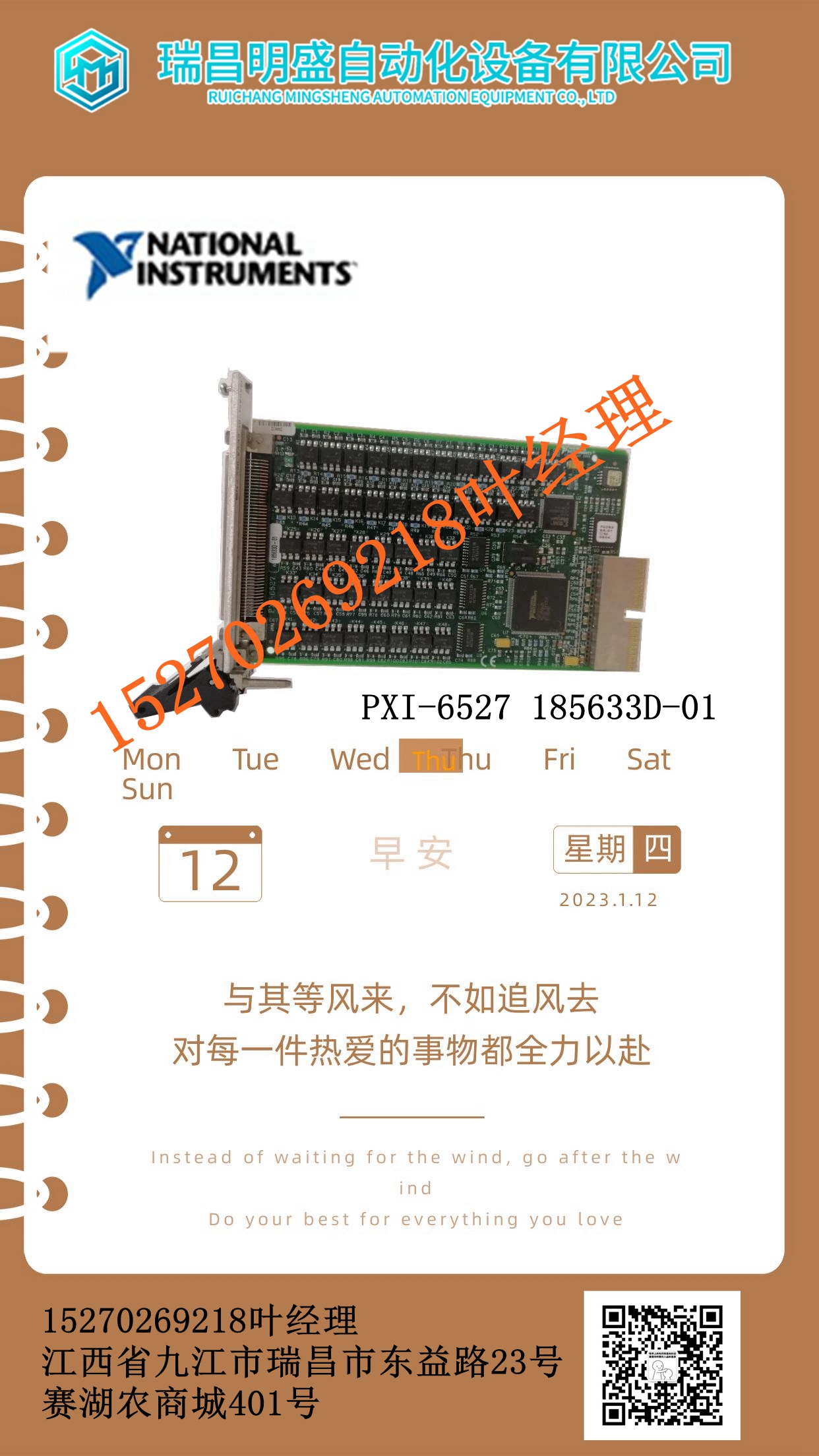
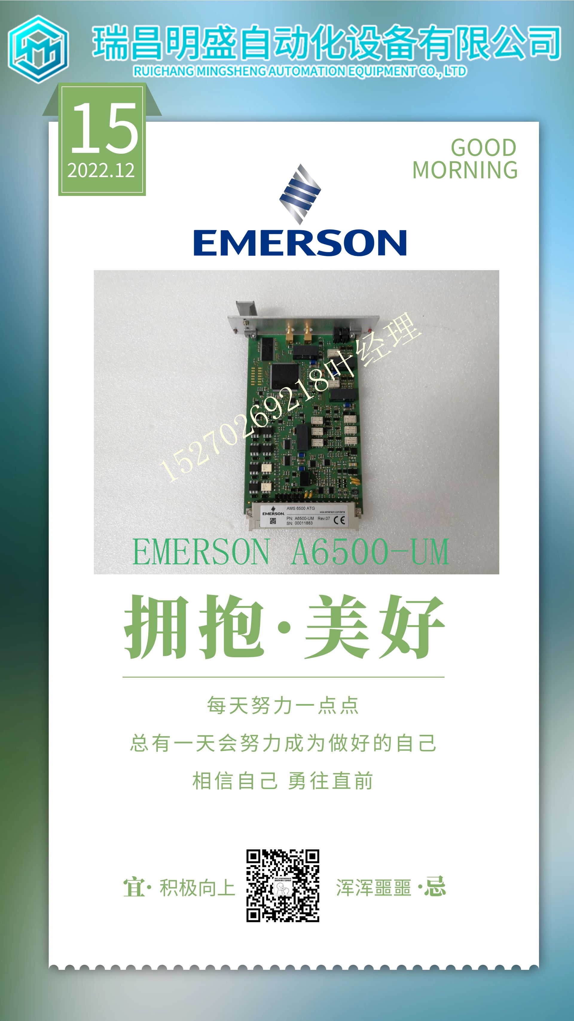
HIEE401481R1 UAC326AE系统模块卡件
g如果该模块的内部温度对于同时打开的输出数量而言过高,则会生成“过热”警报。除了超温故障报告和中断的可配置选项外,超温状态也由该模块状态参考数据中的超温位指示。始终启用过热状态位的检测。PACSystems*RX3i系统手册第12节GFK-2314T 2019年9月带HART通信的模拟模块521模块参数(续)参数默认说明HART数据扫描控制无数据选择CPU是否将自动从HART模块进行扫描:无数据、仅更改数据或每个HARTenabled信道的所有数据。有关内存使用的详细信息,请参阅下文。仅动态数据:每个输入设备的前18个字或288位HART数据。所有数据:所有HART数据(每个HART输入设备88个字或1408位)。HART直通服务选项每两个通道扫描一次选择模块是否会在每次1、2或4通道扫描时自动服务HART直通命令,或仅在更改HART设备配置时,或在10秒内未读取数据时(仅通过)。如果选择“仅通过”,则应用程序无法使用扫描数据。HART状态参考HART启用信道编号X(18字或288位)所有数据最高HART启用信道号X(88字或1408位)I/O扫描集1将模块I/O状态数据分配给CPU配置中定义的扫描集。确定RX3i在未启用/禁用端子块的情况下轮询数据通道故障的频率:控制端子块移除后是否会生成通道故障和配置的报警响应。默认设置为Disabled(禁用)意味着移除接线板时,通道故障和报警被抑制。此参数不影响模块故障,包括接线板丢失/添加故障生成。模块故障报告启用启用启用/禁用。控制模块是否会报告因失去现场电源或温度过高而导致的故障。现场电源移除启用启用启用/禁用。启用模块故障报告后,具有HART通信523 11.3.5.2信道参数参数默认描述范围类型禁用电流的模拟模块设置用于每个信道的输出类型。选项包括:禁用电压、禁用电流、电流/电压。用于HART通信的信道默认力至默认值控制输出在输出禁用模式(停止)下的状态,如果发生故障,如果断电,或如果配置被清除。选项为“保持最后状态”,或默认为特定配置的默认值。11.3.5.2.1量程类型应为电流/电压配置将要使用的模块上的每个通道。然后可以根据需要配置其电压或电流范围和其他参数。如果不使用通道输出且未连接,请选择“禁用”选项。如果通道被禁用,则无需配置其任何其他参数。如果通道连接到电流输出,但未使用,请选择“禁用电流”。这会将该通道的输出电流设置为0mA(该通道的输入电压将为非零)。如果通道连接到电压输出,但未使用,请选择“禁用电压”。这将将该通道的输出电压设置为0V(该通道的输入电流将为非零)。11.3.5.2.2输出默认值如果启用了保持最后状态,当CPU指示输出未启用时,输出将保持其最后命令值,或者如果返回无连接信道2电流返回无连接公共•••I*图317:现场接线差分模式ALG626或ALG628*保持该跳线尽可能短,以将由于导线增加电阻而产生的误差降至最低。该电阻应为25mΩ 或更少。对于差分输入,两个相邻端子连接为一个通道。编号较低的端子充当高侧。电压输入连接在两个相邻的信道IN端子之间,如图317所示。电流输入连接在通道IN+和该通道的电流返回端子之间。此外,通道In-端子和相应的通道电流回路端子之间必须连接一根跨接导线。共用信号接地,提高信道间串扰抗扰度。带HART通信的两个门卡模块516 11.3模拟输出模块8通道电流/电压带HART:IC695ALG728图320:IC695ALD728非隔离模拟电流/电压输出模块IC695ALM728提供8个带HART的可配置电压或电流输出通道
enerates an Over-Temperature alarm if the internal temperature of this module is too great for the number of outputs that are on at the same time. In addition to the configurable options for Over-Temperature fault reporting and interrupts, an over temperature condition is also indicated by the Over-Temperature bit in the Status Reference data of this module. Detection of the Over-temperature status bit is always enabled. PACSystems* RX3i System Manual Section 12 GFK-2314T Sept. 2019 Analog Modules with HART Communications 521 Module Parameters (Continued) Parameter Default Description HART Data Scan Control No data Selects whether the CPU will automatically scan from the HART module: no data, changed data only, or all data for each HARTenabled channel. Refer to the below for details of memory usage. Dynamic Data Only: the first 18 words or 288 bits of HART data per input device. All Data: all of the HART data (88 words or 1408 bits for each HART input device. HART Pass-Through Service Options Once per two channel scans Selects whether the module will automatically service a HART passthrough command each 1, 2, or 4-channel scans or only upon change of HART device configuration, or if data hasn’t been read for 10 seconds (Pass-Through Only). If Pass-Through Only is selected, scan data is not available to the application program. HART Status Reference HART-enabled Channel Number X (18 words or 288 bits) All Data Highest HART-enabled Channel Number X (88 words or 1408 bits) I/O Scan Set 1 Assigns the module I/O status data to a scan set defined in the CPU configuration. Determines how often the RX3i polls the data Channel Faults w/o Terminal Block Disabled Enabled / Disabled: Controls whether channel faults and configured alarm responses will be generated after a Terminal Block removal. The default setting of Disabled means channel faults and alarms are suppressed when the Terminal Block is removed. This parameter does not affect module faults including the Terminal Block loss/add fault generation. Module Fault Reporting Enabled Enabled Enabled / Disabled. Controls whether the module will report faults resulting from either loss of field power or over-temperature conditions. Field Power Removed Enabled Enabled Enabled / Disabled. With Module Fault Reporting enabled, Analog Modules with HART Communications 523 11.3.5.2 Channel Parameters Parameter Default Description Range Type Disabled Current Sets up the type of output to be used for each channel. Choices are: Disabled Voltage, Disabled Current, Current/Voltage. Channels used for HART communications Default Force to Default Value Controls the state the output will be set to in Outputs Disabled mode (stop), if a fault occurs, if power is lost, or if the configuration is cleared. Choices are Hold Last State, or default to a specific configured default value. 11.3.5.2.1 Range Type Each channel on the module that will be used should be configured for Current/Voltage. Its voltage or current range and other parameters can then be configured as needed. If the channel output will not be used and is not wired, select either “Disabled” option. If a channel is disabled, it is not necessary to configure any of its other parameters. If the channel is wired to a current output, but is not being used, select "Disabled Current". This will set the output current for that channel to 0mA (the output voltage for that channel will be non-zero). If the channel is wired to a voltage output, but is not being used, select "Disabled Voltage". This will set the output voltage for that channel to 0V (the output current for that channel will be non-zero). 11.3.5.2.2 Output Defaults If Hold Last State is enabled, an output will hold its last commanded value when the CPU indicates Outputs Not Enabled, or if one of the Return No Connection Channel 2 Current Return No Connection Common • • • I * Figure 317: Field Wiring Differential Mode ALG626 or ALG628 * Keep this jumper as short as possible to minimize error due to the added resistance of the wire. This resistance should be 25mΩ or less. For differential inputs, two adjacent terminals are connected as one channel. The lower-numbered terminal acts as the high side. A voltage input is connected between the two adjacent Channel IN terminals, as shown in Figure 317. A current input is connected between the Channel IN+ and Current Return terminals for that channel. In addition, a jumper wire must be connected between the Channel IN - terminal and the corresponding Channel Current Return terminal. Tie common to signal ground for improved channel-to-channel Crosstalk immunity. Two door cards Modules with HART Communications 516 11.3 Analog Output Module 8-Channel Current/Voltage with HART: IC695ALG728 Figure 320: IC695ALG728 Non-Isolated Analog Current/Voltage Output module, IC695ALG728, provides eight configurable voltage or current output channels with HART


