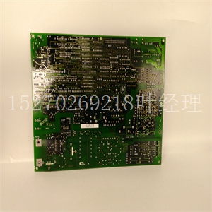
HIEE405053R1 UN0803B-P V1通用电气卡件
PACSystems*RX3i系统手册第12节GFK-2314T 2019年9月带HART通信的模拟模块508 11.2.4.1信道值参考数据:ALG626和ALG628模块在其配置的信道值参考输入字中报告其输入信道数据,从其分配的信道值参考地址开始。每个信道值占用2个字,无论是否使用信道:信道值参考地址包含此输入+0、1信道1+2、3信道2+4、5信道3+6、7信道4+8、9信道5+10、11信道6+12、13信道7+14、15信道8仅用于模块IC695ALG626:+16、17信道9+18、19信道10+20、21信道11+22、23信道12+24、25信道13+26、,27信道14+28、29信道15+30、31信道16根据其配置的信道值格式,每个启用的信道向CPU报告32位浮点或16位整数值。在16位整数模式中,32位通道数据区的低位字包含16位整数通道值。32位值的高位字(高位16位)设置为16位整数的符号扩展。此符号扩展的高位字允许在逻辑中将16位整数读取为32位整数类型,而不丢失整数的符号。如果16位整数结果为负,则32位通道数据中的高位字具有值0xFFFF。如果16位整数结果为正,则高位字为0x0000。PACSystems*RX3i系统手册第12节GFK-2314T 2019年9月带HART通信的模拟模块509 11.2.4.1.1分辨率和量程类型每个输入的实际分辨率取决于为该信道配置的量程类型和A/D滤波器频率。在较高的滤波器频率下,输入分辨率降低。下表显示了每个滤波器频率和范围类型的近似分辨率(以位为单位)。滤波器频率范围类型±10 Vdc 0至10 Vdc、±5 Vdc、±20 Vdc 0至5 Vdc、1Vdc至5 Vdc,0至20mA、4至20mA 8 Hz 18 17 16 12 Hz 17 16 16 16 16 Hz 17 16 40 Hz 16 15 15 14 200 Hz 15 14 13 500 Hz 14 13 12 11.2.4.1.2信道扫描这些模块使用4个A/D转换器实现最快的信道扫描时间。每个模块扫描最多有四个采集周期。采集周期和最快扫描时间,始终按采集周期连线。例如,如果在16通道模块IC695ALG626上仅使用了8个通道,则应使用通道1、2、5、6、9、10、13和14以获得最佳性能。PACSystems*RX3i系统手册第12节GFK-2314T 2019年9月带有HART通信的模拟模块510 11.2.4.2输入信道诊断参考数据:ALG626和ALG628如果模块配置为使用诊断参考地址,则向CPU报告信道诊断状态数据。CPU将该数据存储在为该模块配置的诊断参考地址中。此功能的使用是可选的。每个通道的诊断数据占2个字(信道上是否存在信道条件。当位等于0时,报警或故障条件不存在,或者该信道的配置中未启用检测。对于每个信道,该数据的格式为:PACSystems*RX3i系统手册第12节GFK-2314T 2019年9月带HART通信的模拟模块511 11.2.4.3模块状态参考数据:ALG626和ALG628模块可以可选地被配置为向CPU返回两位模块状态数据。CPU将此数据存储在为该模块配置的32位模块状态参考区域中。运行期间,PLC必须处于I/O启用模式,以便在参考存储器中扫描和更新当前模块状态。11.2.4.3.1接线板检测模块自动检查是否存在接线板。TB LED指示该模块接线板的状态。当接线板存在时,它是绿色的,如果没有,它是红色的。
PACSystems* RX3i System Manual Section 12 GFK-2314T Sept. 2019 Analog Modules with HART Communications 508 11.2.4.1 Channel Value Reference Data: ALG626 and ALG628 The module reports its input channel data in its configured Channel Value Reference input words, beginning at its assigned Channel Value Reference Address. Each channel value occupies 2 words, whether the channel is used or not: Channel Value Reference Address Contains this Input +0, 1 Channel 1 +2, 3 Channel 2 +4, 5 Channel 3 +6, 7 Channel 4 +8, 9 Channel 5 +10, 11 Channel 6 +12, 13 Channel 7 +14, 15 Channel 8 For Module IC695ALG626 Only: +16, 17 Channel 9 +18, 19 Channel 10 +20, 21 Channel 11 +22, 23 Channel 12 +24, 25 Channel 13 +26, 27 Channel 14 +28, 29 Channel 15 +30, 31 Channel 16 Depending on its configured Channel Value Format, each enabled channel reports a 32-bit floating-point or 16-bit integer value to the CPU. In the 16-bit integer mode, the low word of the 32-bit channel data area contains the 16-bit integer channel value. The high word (upper 16-bits) of the 32-bit value is set with the sign extension of the 16-bit integer. This sign-extended upper word allows the 16-bit integer to be read as a 32-bit integer type in logic without losing the sign of the integer. If the 16-bit integer result is negative, the upper word in the 32-bit channel data has the value 0xFFFF. If the 16-bit integer result is positive, the upper word is 0x0000. PACSystems* RX3i System Manual Section 12 GFK-2314T Sept. 2019 Analog Modules with HART Communications 509 11.2.4.1.1 Resolution and Range Type The actual resolution for each input depends on the Range Type and A/D Filter Frequency configured for that channel. At higher Filter Frequencies, input resolution decreases. The approximate resolution in bits for each Filter Frequency and Range Type are displayed in the following table. Filter Frequency Range Type ±10 Vdc 0 to 10 Vdc, ±5Vdc, ±20 Vdc 0 to 5Vdc, 1Vdc to 5Vdc, 0 to 20mA, 4 to 20mA 8 Hz 18 17 16 12 Hz 17 16 15 16 Hz 17 16 15 40 Hz 16 15 14 200 Hz 15 14 13 500 Hz 14 13 12 11.2.4.1.2 Channel Scanning These modules use 4 A/D converters to achieve the fastest possible channel scan times. The module has up to four acquisition cycles for each module scan. The acquisition cycles and For fastest scan times, always wire by acquisition cycle. For example, if only eight channels were used on the 16-channel module, IC695ALG626, channels 1, 2, 5, 6, 9, 10, 13, and 14 should be used for optimum performance. PACSystems* RX3i System Manual Section 12 GFK-2314T Sept. 2019 Analog Modules with HART Communications 510 11.2.4.2 Input Channel Diagnostic Reference Data: ALG626 and ALG628 If the module is configured to use a Diagnostic Reference Address, it reports channel diagnostics status data to the CPU. The CPU stores this data at the Diagnostic Reference Address configured for this module. Use of this feature is optional. The diagnostics data for each channel occupies 2 words (whether the channel condition is present on the channel. When a bit equals 0 the alarm or fault condition is either not present or detection is not enabled in the configuration for that channel. For each channel, the format of this data is: PACSystems* RX3i System Manual Section 12 GFK-2314T Sept. 2019 Analog Modules with HART Communications 511 11.2.4.3 Module Status Reference Data: ALG626 and ALG628 The module can optionally be configured to return two bits of module status data to the CPU. The CPU stores this data in the 32-bit Module Status Reference area configured for this module. During operation, the PLC must be in an I/O Enabled mode for the current Module Status to be scanned and updated in reference memory. 11.2.4.3.1 Terminal Block Detection The module automatically checks for the presence of a Terminal Block. The TB LED indicates the state of the terminal block


