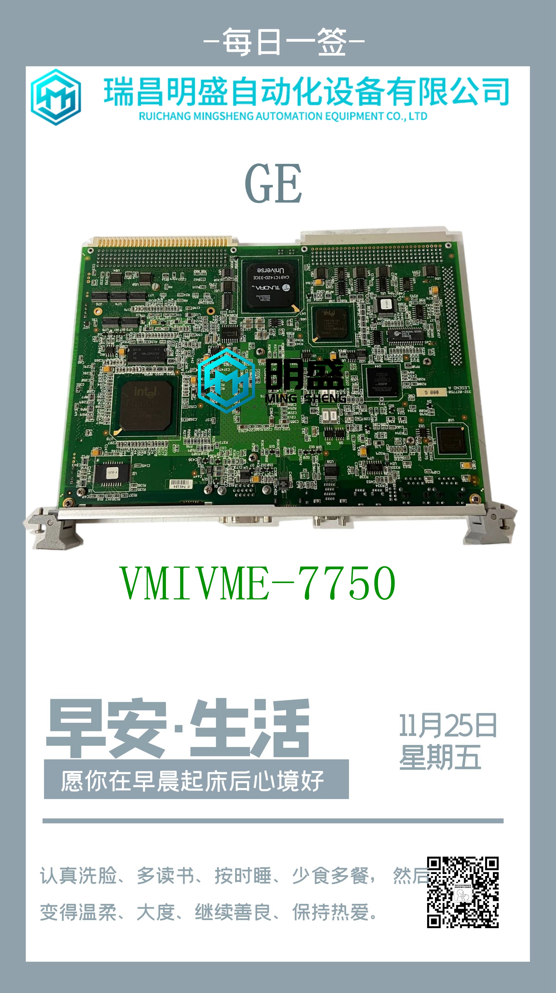
HIMA F2201机器人卡件
VOUT 1 VOUT 2 IOUT 1 IOUT 2 RTN 1 RTN 2 GN D GN D JMPV1 JMPV2 DEF0 0-20mA CH1 CH2 0-20m A*Q1 Q2 NC*NC**+-24V图296:现场接线ALG391在本例中,输出1用作0至5 V范围内的电压输出(JMPV1连接到IOUT1)(已安装range 1跳线),输出2用作4至20 mA模式下的电流输出(未连接JMPV2跳线)。两个输出都将保持最后状态(未安装输出默认跳线,连接外部+24V直流电源)。IOUT2 GND 1 3 5 7 9 11 13 15 17 19 4 8 10 14 16 20 12 2 6 RTN1 RTN2 GND 24V VOUT1 VOUT2 IOUT1 JMPV1 JMPV2输出默认跳线无跳线=保持最后状态[存在=默认为0/4mA]输出1范围选择跳线存在=0至5V(0至0mA)[无跳线=1至5V(4至20mA)]+2K(最小值)输出1用作电压输出。从端子3(IOUT1)连接到端子9(JMPV1)的电压模式跳线输出2用作电流输出。电压模式跳线未连接到端子9(JMPV2)用于保持最后状态输出的外部+24V电源输出2范围选择跳线无跳线=4至20mA(1至5V)[存在=0至0mA(0至5V)]图297:接线示例ALG391 PACSystems*RX3i系统手册第12节GFK-2314T 2019年9月模拟输出模块439 10.2.5.1电流或电压输出每个通道的范围及其通过模块端子上的跳线设置电流或电压模式下的操作。对于电压操作,可以使用250W电阻器代替电压跳线来增加电压范围。下表列出了可以为每个输出设置的输出范围,以及每个范围的跳线或电阻器设置。输出范围跳线安装的模块端子11和13的范围,两个输出默认为其范围的低端。如果未安装输出默认跳线,则两个输出保持从PLC CPU接收的最后一个有效输出值。此选项需要一个外部+24V直流电源,以在系统电源关闭时保持输出功率。PACSystems*RX3i系统手册第12节GFK-2314T 2019年9月模拟输出模块440 10.3模拟输出模块电流/电压8-通道:IC694ALG392模块0K用户电源IC694ALGA392 Q1 Q2 Q3 Q4 Q5 Q6 Q7 Q8图298:IC694A LG392 8通道模拟电流/电压输出模块;IC694ALG392提供多达八个单端输出通道,具有电流回路输出和/或电压输出。可以使用配置软件为以下任何范围设置每个输出通道:▪ 0至+10伏(单极)▪ 10至+10伏(双极)▪ 0至20毫安▪ 4至20毫安每个通道能够将15至16位(取决于所选范围)二进制数据转换为模拟输出。所有八个通道每12毫秒更新一次。在当前模式下,模块向CPU报告每个通道的开路故障。当系统电源中断时,模块可以进入已知的最后状态。只要向模块施加外部电源,每个输出将保持其最后值或重置为零(如配置)。此模块可以安装在RX3i系统的任何I/O插槽中。模块支持插入
VOUT 1 VOUT 2 IOUT 1 IOUT 2 RTN 1 RTN 2 GN D GN D JMPV1 JMPV2 DEF0 0-20mA CH1 CH2 0-20m A * Q1 Q2 NC * NC * * + - 24V Figure 296: Field Wiring ALG391 In this example, Output 1 is used as a voltage output (JMPV1 connected to IOUT1) in the 0 to 5 V range (RANGE 1 jumper installed) Output 2 is used as a current output (JMPV2 not connected) in the 4 to 20 mA mode (RANGE2 jumper not installed). Both outputs will Hold Last State (no Output Default jumper installed, external +24Vdc power supply connected). IOUT2 GND 1 3 5 7 9 11 13 15 17 19 4 8 10 14 16 18 20 12 2 6 RTN1 RTN2 GND 24V VOUT1 VOUT2 IOUT1 JMPV1 JMPV2 Output Default Jumper No jumper = Hold Last State [Present = default to 0/4mA] Output 1 Range Select Jumper Present = 0 to 5V (0 to 0mA) [No jumper = 1 to 5V (4 to 20mA)] + 2K (Minimum) Output 1 Used as Voltage Output. Voltage mode jumper connected from terminal 3 (IOUT1) to terminal 9 (JMPV1) Output 2 Used as Current Output. Voltage mode jumper NOT connected to terminal 9 (JMPV2) External +24V Power Supply for Hold Last State Outputs Output 2 Range Select Jumper No jumper = 4 to 20mA (1 to 5V) [Present = 0 to 0mA (0 to 5V)] Figure 297: Wiring Example ALG391 PACSystems* RX3i System Manual Section 12 GFK-2314T Sept. 2019 Analog Output Modules 439 10.2.5.1 Current or Voltage Outputs The range of each channel and its operation in current or voltage mode are set with jumpers on the module terminals. For voltage operation, a 250W resistor can be used instead of a voltage jumper to increase the voltage range. The following table lists the output ranges that can be set up for each output, and the jumper or resistor settings for each range. Range of the Output Range Jumper Installed module terminals 11 and 13, both outputs default to the low end of their ranges. If the Output Default jumper is not installed, both outputs hold the last valid output value received from the PLC CPU. This option requires an external +24Vdc power supply to maintain output power when the system power goes down. PACSystems* RX3i System Manual Section 12 GFK-2314T Sept. 2019 Analog Output Modules 440 10.3 Analog Output Module Current/Voltage 8- Channel: IC694ALG392 MODULE 0K USER SUPPLY IC694ALG392 Q1 Q2 Q3 Q4 Q5 Q6 Q7 Q8 Figure 298: IC694ALG392 The 8–Channel Analog Current/Voltage Output module; IC694ALG392, provides up to eight single-ended output channels with current loop outputs and/or voltage outputs. Each output channel can be set up using the configuration software for any of these ranges: ▪ 0 to +10 volts (unipolar) ▪ 10 to +10 volts (bipolar) ▪ 0 to 20 milliamps ▪ 4 to 20 milliamps Each channel is capable of converting 15 to 16 bits (depending on the range selected) of binary data to an analog output. All eight channels are updated every 12 ms. In current modes, the module reports an Open Wire fault to the CPU for each channel. The module can go to a known last state when system power is interrupted. As long as external power is applied to the module, each output will maintain its last value or reset to zero, as configured. This module can be installed in any I/O slot of an RX3i system. Module supports insertion


