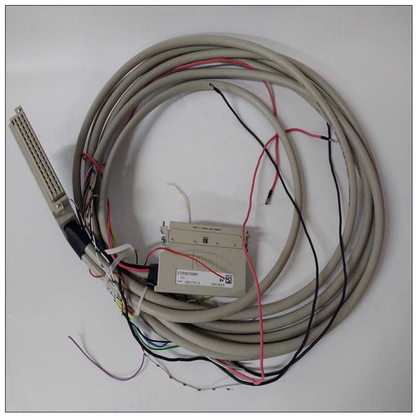
HIMA F3113卡件
l限制。高报警(Eng单位)低报警(Eng单位)低-低报警(Eng单位)高-高报警死区(Eng单元)高报警死区。该值在报警检查之前添加到通道上的缩放值。禁用/启用软件过滤。控制是否对输入执行软件过滤。积分时间(毫秒)0指定软件筛选器达到输入值63.2%的时间量(毫秒)。值为0表示软件过滤器已禁用。值为100表示数据将在100毫秒内达到其值的63.2%。默认值为0。PACSystems*RX3i系统手册第10节GFK-2314T 2019年9月模拟输入模块419 9.11.1.2使用报警:ALG608和ALG616诊断报告启用、故障报告启用和中断启用配置参数可用于为单个通道报警启用不同类型的响应。默认情况下,在每个通道上禁用所有响应。可以为每个通道配置报警启用的任何组合。▪ 如果启用了诊断报告,模块将在该通道的诊断参考地址的参考存储器中报告通道报警。▪ 如果启用了故障报告,则模块会在I/O故障表中记录每次通道报警的故障日志。▪ 如果启用了中断,警报可以触发应用程序中中断块的执行,如下所述。9.11.1.3使用中断:ALG608和ALG616要正确配置I/O中断,必须在模块的配置文件中设置中断启用位。此外,应响应信道中断而执行的程序块必须映射到相应信道的参考地址。示例:在此示例中,通道值参考地址块映射到%AI0001-%AI0020。如果通道2出现高报警条件,应触发I/O中断块。▪ 配置高报警条件。▪ 在模块配置中设置通道2的高报警中断启用标志。通道2的参考地址对应于%AI00003(每个通道2个字),因此应为“I/O中断”类型设置中断程序块调度属性,并将“%AI0003”设置为触发器。9.11.1.3.1故障报告和中断:ALG608和ALG616这些模块具有诊断报告和中断的单独启用/禁用选项。通常,禁用配置中的诊断(如低/高报警或过高/过低范围)意味着其诊断位从未设置。但是,如果为某个条件启用了中断并且发生了该中断,则在I/O中断块逻辑执行期间也会设置该条件的诊断位。下一次PLC输入扫描总是将此中断状态位清除回0,因为诊断报告已禁用。9.11.2模块数据:ALG608和ALG616模块以其配置的输入字报告其输入信道数据,从其分配的信道值参考地址开始。每个信道占用两个字(无论是否使用信道):信道值参考地址包含此输入+0,1信道1 PACSystems*RX3i系统手册第10节GFK-2314T 2019年9月模拟输入模块420+2,3信道2+4,5信道3+6,7信道4+8,9信道5+10,11信道6+12,13信道7+14,15信道8仅用于模块IC695ALG616:+16,17信道9+18,19信道10+20、21信道11+22、23信道12+24、25信道13+26、27信道14+28、29信道15+30、31信道16根据其配置的信道值格式,每个启用的信道向CPU报告32位浮点或16位整数值。在16位整数模式中,32位通道数据区的低位字包含16位整数通道值。32位的高位字(高位16位)
imits. High Alarm (Eng Units) Low Alarm (Eng Units) Low-Low Alarm (Eng Units) High-High Alarm Deadband (Eng Units) High Alarm Deadband (Eng Units) Low Alarm Deadband (Eng Units) Low-Low Alarm Deadband (Eng Units) User Offset 0.0 Engineering Units offset to change the base of the input channel. This value is added to the scaled value on the channel prior to alarm checking. Software Filtering Disabled Disabled / Enabled. Controls whether software filtering will be performed on the inputs. Integration Time (ms) 0 Specifies the amount of time in milliseconds for the software filter to reach 63.2% of the input value. A value of 0 indicates software filter is disabled. A value of 100 indicates data will achieve 63.2% of its value in 100ms. Default is 0. PACSystems* RX3i System Manual Section 10 GFK-2314T Sept. 2019 Analog Input Modules 419 9.11.1.2 Using Alarming: ALG608 & ALG616 The Diagnostic Reporting Enable, Fault Reporting Enable, and Interrupt Enable configuration parameters can be used to enable different types of responses for individual channel alarms. By default, all responses are disabled on every channel. Any combination of alarm enables can be configured for each channel. ▪ If Diagnostic Reporting is enabled, the module reports channel alarms in reference memory at the Diagnostic Reference address for that channel. ▪ If Fault Reporting is enabled, the module logs a fault log in the I/O Fault table for each occurrence of a channel alarm. ▪ If Interrupts are enabled, an alarm can trigger execution of an Interrupt Block in the application program, as explained below. 9.11.1.3 Using Interrupts: ALG608 & ALG616 To properly configure an I/O Interrupt, the Interrupt enable bit or bits must be set in the configuration profile of the module. In addition, the program block that should be executed in response to the channel interrupt must be mapped to the reference address of the corresponding channel. Example: In this example, the Channel Values Reference Address block is mapped to %AI0001-%AI0020. An I/O Interrupt block should be triggered if a High Alarm condition occurs on channel 2. ▪ Configure the High-Alarm condition. ▪ Set the High-Alarm Interrupt Enable flag for Channel 2 in the module configuration. The reference address for Channel 2 corresponds to %AI00003 (2 Words per channel), so the interrupt program block Scheduling properties should be set for the "I/O Interrupt" Type and "%AI0003" as the Trigger. 9.11.1.3.1 Fault Reporting and Interrupts: ALG608 & ALG616 These modules have separate enable/disable options for Diagnostic Reporting and Interrupts. Normally, disabling a diagnostic (such as Low/High Alarm or Over/Under range) in the configuration means that its diagnostic bit is never set. However, if interrupts are enabled for a condition and that interrupt occurs, the diagnostic bit for that condition is also set during the I/O Interrupt block logic execution. The next PLC input scan always clears this interrupt status bit back to 0, because Diagnostic Reporting has it disabled. 9.11.2 Module Data: ALG608 & ALG616 The module reports its input channel data in its configured input words, beginning at its assigned Channel Value Reference Address. Each channel occupies two words (whether the channel is used or not): Channel Value Reference Address Contains this Input +0, 1 Channel 1 PACSystems* RX3i System Manual Section 10 GFK-2314T Sept. 2019 Analog Input Modules 420 +2, 3 Channel 2 +4, 5 Channel 3 +6, 7 Channel 4 +8, 9 Channel 5 +10, 11 Channel 6 +12, 13 Channel 7 +14, 15 Channel 8 For Module IC695ALG616 Only: +16, 17 Channel 9 +18, 19 Channel 10 +20, 21 Channel 11 +22, 23 Channel 12 +24, 25 Channel 13 +26, 27 Channel 14 +28, 29 Channel 15 +30, 31 Channel 16 Depending on its configured Channel Value Format, each enabled channel reports a 32-bit floating-point or 16-bit integer value to the CPU. In the 16-bit integer mode, the low word of the 32-bit channel data area contains the 16-bit integer channel value. The high word (upper 16-bits) of the 32-bit


