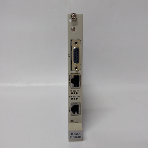
HIMA F3213A工控DCS系统备件
报警和低低报警:当达到或超过配置值时,将触发低低报警或高高报警。配置值必须低于/高于相应的低/高报警限值。高报警和低报警:当达到或低于(高于)配置值时,将触发低(高)报警。高报警死区和低报警死区:工程单位中高于报警条件(低死区)或低于报警条件(高死区)的范围,即使报警条件消失,报警状态位也可以保持设置。要清除报警状态,通道输入必须超出死区范围。报警死区不应导致报警清除条件超出工程单位用户限制范围。例如,如果通道的工程单位范围为-1000.0至+1000.0,且高报警设置为+100.00,则高报警死区值范围为0.0至小于1100.0。1100.0或更大的死区将使高报警清除条件低于–1000.0单位,从而使报警无法在限制范围内清除。高报警(Eng单位)低报警(Eng单位)低-低报警(Eng单位)高-高报警死区(Eng单元)高-低报警死区(Eng单元)低-报警死区(Eng单元)用户偏移16位整数范围:-32768到32768 32位浮点,范围:-3.40282e+38到3.40282e+38。0.0(默认值)工程单位偏移以更改输入通道的基础。该值在报警检查之前添加到通道上的缩放值。软件过滤已禁用(默认)或已启用控制是否对输入执行软件过滤。PACSystems*RX3i系统手册第10节GFK-2314T 2019年9月模拟输入模块403积分时间(ms)0(默认值)到4294967295 ms指定软件滤波器达到输入值63.2%的时间量(毫秒)。值为0表示软件过滤器已禁用。值为100表示数据将在100毫秒内达到其值的63.2%。诊断报告启用禁用(默认)或启用(仅当在设置选项卡上启用模块级诊断报告时可用)。如果启用了诊断报告,模块将在诊断参考存储器中报告通道报警。可以单独启用通道报警。故障报告启用如果启用了故障报告,则模块会在I/O故障表中记录每次发生通道报警的故障日志。可以单独启用通道报警的故障报告。9.9.5.3输入缩放:ALG233在4至20 mA范围内,输入数据进行缩放,使4 mA对应于0的计数,20 mA对应于32000的计数。在0至20mA范围内,
Alarm and Low-Low Alarm: When the configured value is reached or passed, a Low-Low Alarm or High-High Alarm is triggered. The configured values must be lower than/higher than the corresponding low/high alarm limits. High Alarm and Low Alarm: When the configured value is reached or below (above), a Low (High) Alarm is triggered. High and Low Alarm Deadbands: A range in Engineering Units above the alarm condition (low deadband) or below the alarm condition (high deadband) where the alarm status bit can remain set even after the alarm condition goes away. For the alarm status to clear, the channel input must fall outside the deadband range. Alarm Deadbands should not cause the alarm clear condition to be outside the Engineering Unit User Limits range. For example, if the engineering unit range for a channel is -1000.0 to +1000.0 and a High Alarm is set at +100.0, the High Alarm Deadband value range is 0.0 to less than 1100.0. A deadband of 1100.0 or more would put the High Alarm clear condition below –1000.0 units making the alarm impossible to clear within the limits. High Alarm (Eng Units) Low Alarm (Eng Units) Low-Low Alarm (Eng Units) High-High Alarm Deadband (Eng Units) High Alarm Deadband (Eng Units) Low Alarm Deadband (Eng Units) Low-Low Alarm Deadband (Eng Units) User Offset 16-bit Integer range: -32768 through 32768 32-bit Floating-point, range: -3.40282e+38 through 3.40282e+38. 0.0 (default) Engineering Units offset to change the base of the input channel. This value is added to the scaled value on the channel prior to alarm checking. Software Filtering Disabled (default) or Enabled Controls whether software filtering will be performed on the inputs. PACSystems* RX3i System Manual Section 10 GFK-2314T Sept. 2019 Analog Input Modules 403 Integration Time (ms) 0 (default) through 4,294,967,295 ms Specifies the amount of time in milliseconds for the software filter to reach 63.2% of the input value. A value of 0 indicates software filter is disabled. A value of 100 indicates data will achieve 63.2% of its value in 100ms. Diagnostic Reporting Enable Disabled (default) or Enabled (Available only if Module Level Diagnostic Reporting is enabled on the Settings tab.) If Diagnostic Reporting is enabled, the module reports channel alarms in the Diagnostic Reference memory. Channel alarms can be individually enabled. Fault Reporting Enable If Fault Reporting is enabled, the module logs a fault log in the I/O Fault table for each occurrence of a channel alarm. Fault reporting for channel alarms can be individually enabled. 9.9.5.3 Input Scaling: ALG233 In the 4 to 20 mA range, input data is scaled so that 4 mA corresponds to a count of 0 and 20 mA corresponds to a count of 32000. In the 0 to 20 mA range,


