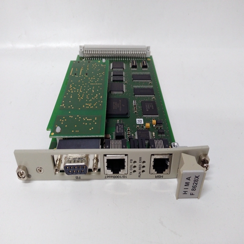
HIMA F3334处理器卡件,工控自动化卡件
0 1 2 3 4 5 6 7 8 9 10 11 12插槽编号图58:RX3i通用背板PACSystems的功能*RX3i系统手册第4节GFK-2314T 2019年9月背板73 RX3i的通用背板功能包括:▪ 左侧的接线板(图58)用于隔离+24V直流输入。▪ 背板接地点,如第0节所述。▪ 用于连接模块/屏蔽接地的整体接地棒,如第2.5.5节所述。▪ 可拆卸的盖子,当被敲出时,允许插入配有散热器的模块上的散热器。▪ 用于连接串行扩展和远程背板(仅限12和16插槽型号)的串行扩展连接器(图58,最右侧)。▪ 插槽编号印在背板上(图58),用于Proficy Machine Edition(PME)中的配置参考。插槽和连接器在以下页面中进行了描述。大多数模块占用一个插槽。一些模块(如CPU和交流电源)占用两个插槽。PACSystems*RX3i系统手册第4节GFK-2314T 2019年9月背板74 3.1.1.1通用背板TB1输入端子RX3i IC695电源不通过背板提供隔离+24V直流输出电源。端子7和8可用于连接可选的隔离+24V直流外部电源,这是第4.2节模块负载要求表中列出的一些IC693和IC694模块所需的。这些端子接受14至22 AWG的单独导线。如果需要隔离+24Vdc的模块安装在扩展背板中,则不需要外部隔离+24Vdc电源。未使用端子1至6。1–6:未使用7:隔离+24V DC输入8:隔离接地0 1 TB 1 1 8插槽0:仅用于RX3i IC695电源的连接器图59:TB1端子详图3.1.1.2插槽0通用背板中最左侧的插槽是插槽0。只有IC695电源的背板连接器可以安装在插槽0中(注意:IC695可以安装在任何插槽中)。然而,具有右对齐连接器的2槽宽模块(如CPU310)可以插入插槽1,也可以覆盖插槽0。对于配置和应用程序逻辑,CPU由整个模块占用的最左侧插槽引用,而不是由物理连接器所在的插槽引用。例如,如果CPU将其物理连接器插入插槽3,则模块占用插槽2和3,而CPU被引用为位于插槽2中。因此,双宽CPU可以位于插槽0中,其背板连接器插入插槽1中。3.1.1.3双连接器插槽PACSystems*RX3i系统手册第4节GFK-2314T 2019年9月背板75双连接器插槽标识如下:CHS016:0至15 CHS012:0至11 CHS007:0至5它们有两个连接器,一个用于RX3i PCI总线的连接器,另一个用于RX3i串行总线的连接器。每个插槽都可以接受任何类型的兼容模块:IC695电源、IC695 CPU或IC695、IC694和IC693 I/O或选件模块。如果仔细遵循第2.6.4.1节所述的热插拔程序,则可以在不断电的情况下拆除和更换通用背板中的I/O和选件模块。10用于串行总线的PCI总线连接器图60:RX3i通用背板用于PCI总线和串行总线的双连接器插槽PACSystems*RX3i系统手册第4节GFK-2314T 2019年9月背板76 3.1.1.4扩展插槽(插槽12或插槽16)通用背板中最右侧的插槽具有与其他插槽不同的连接器。它只能用于RX3i串行扩展模块IC695LRE001。RX3i 2插槽模块可能不会占用此扩展插槽。7插槽CHS007机架不提供扩展插槽,也不支持LRE001串行扩展模块。11 12 E X P A N S I O N图61:7插槽机架PACSystems*RX3i系统手册第4节GFK-2314T 2019年9月背板77中插槽12 3.1.1.5插槽6所示的扩展插槽连接器在CHS007 7插槽机架中,插槽6有一个RX3i PCI连接器,只能接受IC695单宽I/O或选件模块。5 6图62:12或16插槽通用背板中IC695CHS007 3.1.2模块的插槽6位置▪ IC695电源模块可以安装在任何插槽中。直流电源IC695PSDx40占用一个插槽,交流电源IC695PSA x40占用两个插槽。
0 1 2 3 4 5 6 7 8 9 10 11 12 Slot Numbers Figure 58: Features of RX3i Universal Backplanes PACSystems* RX3i System Manual Section 4 GFK-2314T Sept. 2019 Backplane 73 RX3i Universal Backplane features include: ▪ Terminal Strip on the left (Figure 58) for Isolated +24Vdc input. ▪ Backplane grounding point as described in Section 0. ▪ An integral grounding bar for connecting module/shield grounds as described in Section 2.5.5. ▪ Removable covers that, when knocked out, allow heat sinks on modules equipped with heat sinks to be inserted. ▪ Serial Expansion connector for connection (Figure 58, far right) to Serial Expansion and Remote Backplanes (12- and 16-slot models only). ▪ Slot numbers are printed on the backplane (Figure 58) and are used for reference for configuration in Proficy Machine Edition (PME). Slots and connectors are described on the following pages. Most modules occupy one slot. Some modules, such as CPUs and AC Power Supplies occupy two slots. PACSystems* RX3i System Manual Section 4 GFK-2314T Sept. 2019 Backplane 74 3.1.1.1 Universal Backplane TB1 Input Terminals The RX3i IC695 Power Supplies do not provide Isolated +24Vdc output power over the backplane. Terminals 7 and 8 can be used to connect an optional external source of Isolated +24Vdc, which is required for some IC693 and IC694 modules as listed in the table, Module Load Requirements, Section 4.2. These terminals accept individual wires from 14 to 22 AWG. If modules that require Isolated +24Vdc are installed in an Expansion Backplane instead, an external Isolated +24Vdc power supply is not required. Terminals 1 through 6 are not used. 1 – 6: not used 7: Isolated +24VDC In 8: Isolated Ground 0 1 TB 1 1 8 Slot 0: Connector for RX3i IC695 Power Supply only Figure 59: TB1 Terminal Detail 3.1.1.2 Slot 0 The leftmost slot in a Universal Backplane is slot 0. Only the backplane connector of IC695 Power Supplies can be installed in slot 0 (note: IC695 Power Supplies can be installed any slot). However, 2-slot wide modules that have right-justified connectors, such as the CPU310, can be plugged into slot 1and also cover slot 0. The CPU is referenced for configuration and application logic by the leftmost slot occupied by the entire module, not by the slot the physical connector is located in. For example, if the CPU has its physical connector inserted in slot 3, the module occupies slots 2 and 3 and the CPU is referenced as being located in slot 2. A double-wide CPU may therefore be located in slot 0 with its backplane connector inserted in slot 1. 3.1.1.3 Dual-Connector Slots PACSystems* RX3i System Manual Section 4 GFK-2314T Sept. 2019 Backplane 75 Dual-connector slots are identified as follows: CHS016: 0 through 15 CHS012: 0 through 11 CHS007: 0 through 5 They have two connectors, a connector for the RX3i PCI bus, and connector for the RX3i serial bus. Each of these slots can accept any type of compatible module: IC695 Power Supply, IC695 CPU, or IC695, IC694 and IC693 I/O or option modules. Provided the Hot Insertion and Removal procedure described in Section 2.6.4.1 is carefully followed, I/O and option modules in a Universal Backplane may be removed and replaced without powering-down. 10 Connector for PCI Bus Connector for Serial Bus Figure 60: RX3i Universal Backplane Dual Connector Slot for PCI Bus & Serial Bus PACSystems* RX3i System Manual Section 4 GFK-2314T Sept. 2019 Backplane 76 3.1.1.4 Expansion Slot (Slot 12 or Slot 16) The rightmost slot in a Universal Backplane has a different connector than the other slots. It can only be used for an RX3i Serial Expansion Module, IC695LRE001. An RX3i 2-slot module may not occupy this expansion slot. The 7-slot CHS007 rack does not provide an expansion slot, or support the LRE001 Serial Expansion Module. 11 12 E X P A N S I O N Figure 61: Expansion Slot Connector shown at Slot 12 3.1.1.5 Slot 6 of 7-Slot Rack PACSystems* RX3i System Manual Section 4 GFK-2314T Sept. 2019 Backplane 77 In the CHS007 seven-slot rack, slot 6 has one RX3i PCI connector and can accept only IC695 single-width I/O or option modules. 5 6 Figure 62: Slot 6 of IC695CHS007 3.1.2 Module Locations in a 12- or 16-Slot Universal Backplane ▪ IC695 Power Supply modules may be installed in any slot. DC Power Supplies IC695PSDx40 occupy one slot and AC Power Supplies IC695PSAx40 occupy two slots.


