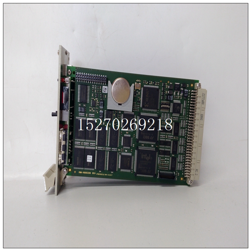
HIMA F6217 Z7127 模块控制器
这对于未安装在同一控制柜中的背板尤为重要。警告:除了遵守此处所述的接地程序外,还必须遵守当地接地规范。在美国,大多数地区都采用了国家电气规范标准,并规定所有布线都符合其要求。在其他国家,适用不同的法规。为确保人员和财产的最大安全,请遵循这些规范。未能做到这一点可能意味着人员受伤或死亡、财产损失或两者兼而有之。除了遵守系统接地程序外,还应定期检查接地连接,以确保系统保持正确接地。▪ PLC设备、其他控制设备和机器应相互连接,以保持公共接地参考,也称为机器底盘接地。PACSystems*RX3i系统手册第3节GFK-2314T 2019年9月安装27个中央接地点电机驱动器和其他电气控制设备机器PLC机柜编程设备信号和电源连接未显示注释接地机架图12:系统接地2.5.1接地导体应以树形方式连接,并将分支布线至中心接地点,如前一页所示。这确保了没有接地导体从任何其他分支输送电流。从系统所有部件到接地的低电感路径可最大限度地减少排放,并提高对电气干扰的免疫力。接地导体应尽可能短,尺寸尽可能大。可使用编织带(建议最大长宽比为10:1)或接地电缆(通常为绿色绝缘,带黄色示踪物-AWG#12(3.3 mm2)或更大),以将电阻降至最低。导体必须始终足够大,以承载所考虑路径的最大短路电流。PACSystems*RX3i系统手册第3节GFK-2314T 2019年9月安装28 2.5.2背板安全和EMC参考接地背板的金属背面必须使用单独的导体接地;背板安装螺钉本身不能提供足够的接地连接。至少使用带有环形端子和星形锁紧垫圈的AWG#12(3.3 mm2)导线。使用机器螺钉、星形锁紧垫圈和平垫圈将接地线的另一端连接到安装面板上的螺纹孔。或者,如果面板有接地螺柱,则为接地螺上的每根导线使用螺母和星形锁紧垫圈,以确保充分接地。当连接到涂漆面板时,应清除油漆,使其干净,裸露金属暴露在连接点。所用端子和硬件的额定值应与铝背板材料配合使用。警告所有背板必须接地,以尽量减少触电危险。否则可能导致严重的人身伤害。图13:接地母线安装PLC系统中组合在一起的所有背板必须具有公共接地连接。这对于未安装在同一控制柜中的背板尤为重要。2.5.3电源接地参考“电源现场接线”一节。2.5.4编程器接地为了正常运行,运行PLC软件的计算机(编程器)必须具有与CPU共用的接地连接。通常,这种公共接地连接是通过将编程设备的电源线连接到与背板相同的电源(具有相同的接地参考点)来实现的。如果编程器接地电位与PLC接地电位不同,则可能存在电击危险。此外,当编程器串行电缆连接在两者之间时,可能会损坏端口。2.5.5屏蔽接地PACSystems*RX3i系统手册第3节GFK-2314T 2019年9月安装29通常,铝PLC背板用于模块屏蔽接地。在某些模块上,模块上用户终端连接器的屏蔽连接通过模块的背板连接器路由到背板。其他模块(如DSM314)需要单独的屏蔽接地,如本手册中的模块说明所示。对于安装在通用背板中的模块,屏蔽接地可使用尺寸为M3的螺钉连接至背板底部的接地棒。建议的最大扭矩为0.45 Nm(4 in-lb)。RX3i通用背板2.6系统安装2.6.1通用背板上的接地棒使用四个优质8-32 x 1/2(4 x 12mm)机器螺钉、锁紧垫圈和平垫圈安装通用背板。将螺钉安装在下图所示的四个螺纹孔中。
This is especially important for backplanes that are not mounted in the same control cabinet. WARNING In addition to observing the grounding procedures described here, it is important to follow local grounding codes. In the United States, most areas have adopted the National Electrical Code standard and specify that all wiring conform to its requirements. In other countries, different codes apply. For maximum safety to personnel and property, follow these codes. Failure to do so can mean injury or death to personnel, damage to property, or both. In addition to observing the system grounding procedures, periodic inspections of the ground connections should be performed to ensure that the system remains properly grounded. ▪ The PLC equipment, other control equipment, and the machine should be interconnected to maintain a common earth ground reference, also called the machine chassis ground. PACSystems* RX3i System Manual Section 3 GFK-2314T Sept. 2019 Installation 27 CENTRAL GROUND POINT MOTOR DRIVES AND OTHER ELECTRICAL CONTROL EQUIPMENT MACHINERY PLC CABINET PROGRAMMING DEVICE SIGNAL AND POWER CONNECTIONS ARE NOT SHOWN NOTE EARTH GROUND RACK RACK Figure 12: System Grounding 2.5.1 Ground Conductors Ground conductors should be connected in a tree fashion with branches routed to a central earth ground point, as shown on the previous page. This ensures that no ground conductor carries current from any other branch. A low inductance path from all parts of a system to earth minimizes emissions and increases immunity to electrical interferences. Ground conductors should be as short and as large in size as possible. Braided straps (maximum 10:1 length to width ratio recommended) or ground cables (typically green insulation with a yellow tracer - AWG #12 (3.3 mm2 ) or larger) can be used to minimize resistance. Conductors must always be large enough to carry the maximum short circuit current of the path being considered. PACSystems* RX3i System Manual Section 3 GFK-2314T Sept. 2019 Installation 28 2.5.2 Backplane Safety and EMC Reference Grounding The metal back of the backplane must be grounded using a separate conductor; the backplane mounting screws alone do not provide an adequate ground connection. At a minimum, use AWG #12 (3.3 mm2 ) wire with a ring terminal and star lock-washer. Connect the other end of this ground wire to a tapped hole in the mounting panel using a machine screw, star lock washer, and flat washer. Alternately, if the panel has a ground stud, use a nut and star lock washer for each wire on the ground stud to ensure adequate grounding. Where connections are made to a painted panel, the paint should be removed so clean, bare metal is exposed at the connection point. Terminals and hardware used should be rated to work with the aluminum backplane material. WARNING All backplanes must be grounded to minimize electrical shock hazard. Failure to do so can result in severe personal injury. Figure 13: Ground Strap Installation All backplanes grouped together in the PLC system must have a common ground connection. This is especially important for backplanes that are not mounted in the same control cabinet. 2.5.3 Power Supply Grounding Refer to the section, Power Supply Field Wiring. 2.5.4 Programmer Grounding For proper operation, the computer (programmer) running the PLC software must have a ground connection in common with the CPU. Normally, this common ground connection is provided by connecting the power cord of the programming device to the same power source (with the same ground reference point) as the backplane. If the programmer ground is at a different potential than the PLC ground, a shock hazard could exist. Also, damage to the ports could occur when the programmer serial cable is connected between the two. 2.5.5 Shield Grounding PACSystems* RX3i System Manual Section 3 GFK-2314T Sept. 2019 Installation 29 In general, the aluminum PLC backplane is used for module shield grounding. On some modules, shield connections to the user terminal connector on the module are routed to the backplane through the backplane connector of the module. Other modules, such as the DSM314 require a separate shield ground, as displayed in the module descriptions in this manual. For modules installed in a Universal Backplane, shield grounds can be connected to the Grounding Bar at the bottom of the Backplane using size M3 screws. The recommended torque is 0.45 Nm (4 in-lb) maximum. Grounding Bar on RX3i Universal Backplane 2.6 System Installation 2.6.1 Universal Backplanes Mount a Universal Backplane using four good quality 8-32 x 1/2 (4 x 12mm) machine screws, lock washers and flat washers. Install the screws in the four tapped holes displayed in the following figure.


