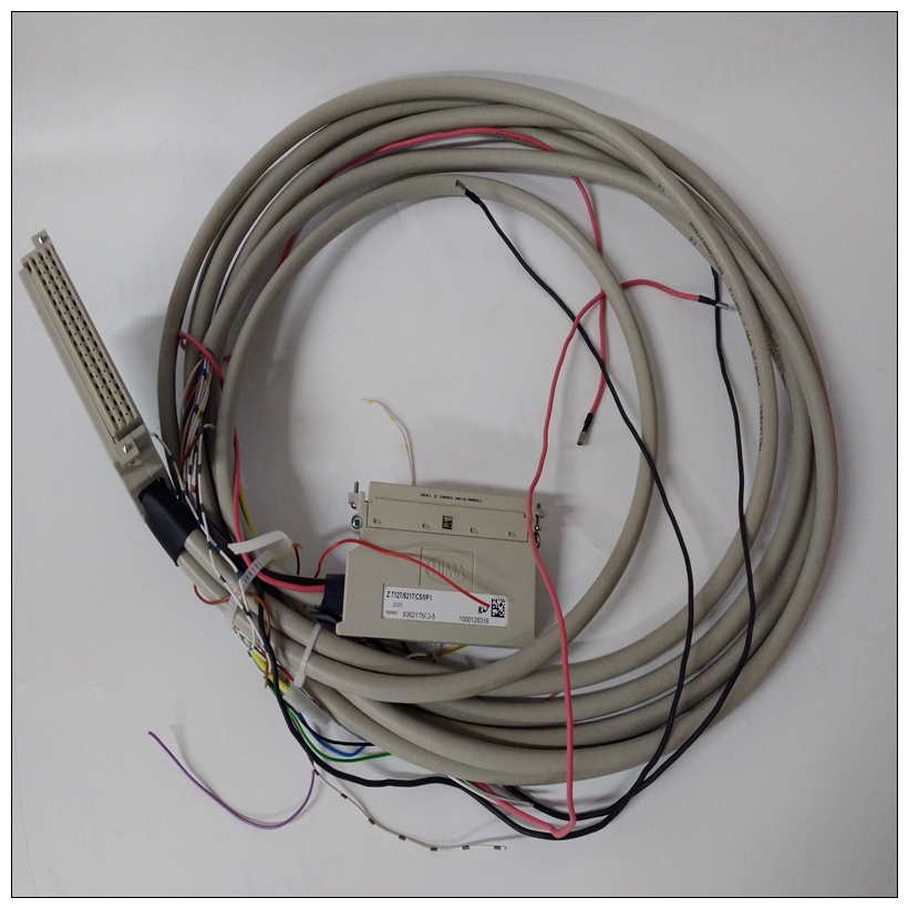
HIMA F8650模块控制器
(仅限12槽和16槽通用背板)图2:LRE001每当应用程序需要比所选通用背板所能容纳的模块更多的模块时,或者当某些模块必须安装在其他位置时,必须在通用背板的最后一个插槽中安装RX3i串行总线发射器模块IC695LRE001(图2)。请注意,只有12插槽和16插槽通用背板可容纳LRE001。总线发送器模块(LRE001)通过电缆连接到第一个扩展或远程背板。后续机架使用电缆菊花链连接在一起(见图5至图7)。D连接器(右侧,图3)用于将Rx3i串行扩展背板连接到LRE001。远程背板也可以以这种方式连接到RX3i系统。图3:5插槽RX3i串行扩展背板IC694CHS398扩展和远程背板的使用总结如下。有关串行总线发射器模块和电缆的更多信息,请参阅第5节:。PACSystems*RX3i系统手册第2节GFK-2314T 2019年9月简介14 1.4.3可用于RX3i通用系统的背板和与RX3i兼容的扩展背板如下所示。有关RX3i背板的说明和规格,请参阅本手册第3章。有关90-30系列扩展背板的信息,请参阅GFK-0898《90-30系列I/O模块规格手册》。背板RX3i 16插槽通用背板IC695CHS016 RX3i 12插槽通用背板ICM695CHS012 RX3i 7插槽通用背板IC 695CHS007 RX3i 10插槽串行扩展背板IC694CHS392 RX3i 5插槽串行扩展底板IC694CHS398系列90-30 10插槽扩展背板IC691CHS392系列90-30 5插槽扩展背板IC 693CHS398系列90-30 10插槽远程扩展背板IC693CHS393系列90-30 5插槽远程扩展背板IC693C HS399 PACSystems*RX3i系统手册第2节GFK-2314T 2019年9月简介15 1.4.4 RX3i电源系统通用和串行扩展背板电源如下所示。请参阅第4章了解RX3i电源的说明和规格。有关Series 90-30电源的信息,请参阅GEK-0898,Series 90-30 I/O Module Specifications Manual。n如果系统仅包括扩展背板,则从CPU到最后一个背板的总距离不能超过15米(50英尺)n如果系统包括任何远程背板,则CPU到最后背板的总长度不能超过213米(700英尺)。远程背板在更远的距离上提供与扩展背板相同的功能。远程背板具有额外的隔离电路,可减少背板彼此相距较远且不共享同一接地系统时可能出现的不平衡接地条件的影响。CPU和远程背板之间的通信可能比CPU和扩展背板之间的时间稍长。与总CPU扫描时间相比,此延迟通常很小。PACSystems*RX3i系统手册第2节GFK-2314T 2019年9月简介17 1.5.1带一个扩展或远程背板的扩展系统扩展系统可由一个仅带一个扩充或远程背板。此示例包括一个通用背板IC695CHS012和一个扩展背板IC694CHS392。本例中的每个背板都有一个直流电源。它们总共容纳19个离散、模拟和特殊功能模块。这些背板相距15米(50英尺)。它们通过具有内置端接电阻器的扩展电缆IC693CBL302连接。如果需要将第二个背板定位在距离通用背板15米(50英尺)以上的位置,则Series 90-30远程背板可与定制长度电缆和外部终端电阻器一起使用。通用背板一扩展背板I/O扩展电缆IC693CBL302电缆长度:15米(50英尺)图
(12-slot and 16-slot Universal Backplanes Only) Figure 2: LRE001 Whenever an application requires more modules than the selected Universal Backplane can accommodate, or whenever some modules must be installed in another location, an RX3i Serial Bus Transmitter Module, IC695LRE001 (Figure 2), must be installed in the last slot of the Universal Backplane. Note that only 12-slot and 16-slot Universal Backplanes accommodate the LRE001. The Bus Transmitter module (LRE001) is connected to the first Expansion or Remote backplane via a cable. Subsequent racks are daisy-chained together using cables (see Figure 5 through Figure 7). The D-connector (right side, Figure 3) is used to connect the Rx3i Serial Expansion backplane to the LRE001. Remote Backplanes may also be connected to the RX3i system in this manner. Figure 3: 5-Slot RX3i Serial Expansion Backplane IC694CHS398 Use of Expansion and Remote Backplanes is summarized on the following pages. For more information about the Serial Bus Transmitter module and cables, refer to Section 5:. PACSystems* RX3i System Manual Section 2 GFK-2314T Sept. 2019 Introduction 14 1.4.3 Backplanes Available for the RX3i System Universal and Expansion Backplanes that are compatible with RX3i systems are listed below. Refer to Chapter 3 of this manual for descriptions and specifications of the RX3i Backplanes. For information about Series 90- 30 Expansion Backplanes, refer to the Series 90-30 I/O Modules Specifications Manual, GFK-0898. Backplanes RX3i 16-Slot Universal Backplane IC695CHS016 RX3i 12-Slot Universal Backplane IC695CHS012 RX3i 7-Slot Universal Backplane IC695CHS007 RX3i 10-Slot Serial Expansion Backplane IC694CHS392 RX3i 5-Slot Serial Expansion Backplane IC694CHS398 Series 90-30 10-Slot Expansion Backplane IC693CHS392 Series 90-30 5-Slot Expansion Backplane IC693CHS398 Series 90-30 10-Slot Remote Expansion Backplane IC693CHS393 Series 90-30 5-Slot Remote Expansion Backplane IC693CHS399 PACSystems* RX3i System Manual Section 2 GFK-2314T Sept. 2019 Introduction 15 1.4.4 Power Supplies for RX3i Systems Power Supplies for Universal and Serial Expansion Backplanes are listed below. Refer to Chapter 4 for descriptions and specifications of the RX3i Power Supplies. For information about Series 90-30 Power Supplies the GEK-0898, Series 90-30 I/O Module Specifications Manual. n If the system includes only Expansion Backplanes, the total distance from the CPU to the last backplane cannot be more than 15 meters (50 feet) n If the system includes any Remote Backplanes, the total distance from the CPU to the last backplane cannot be more than 213 meters (700 feet). Remote Backplanes provide the same functionality as Expansion Backplanes over a much greater distance. Remote Backplanes have extra isolation circuitry that lessens the effect of unbalanced ground conditions that can occur when backplanes are located long distances from each other and do not share the same ground system. Communications between the CPU and a Remote Backplane may take slightly longer than communications between the CPU and an Expansion Backplane. This delay is usually small compared to the total CPU scan time. PACSystems* RX3i System Manual Section 2 GFK-2314T Sept. 2019 Introduction 17 1.5.1 Expansion System with One Expansion or Remote Backplane An Expansion system can consist of a Universal Backplane with just one Expansion or Remote Backplane. This example includes one Universal Backplane IC695CHS012 and one Expansion Backplane, IC694CHS392. Each Backplane in this example has a DC Power Supply. Together, they accommodate 19 discrete, analog, and specialfunction modules. These backplanes are located 15m (50 ft) apart. They are connected via an Expansion Cable IC693CBL302, which has a built-in terminating resistor. If it were necessary to locate the second backplane more than 15m (50 ft) from the Universal Backplane, a Series 90-30 Remote Backplane could be used with a custom-length cable and external terminating resistor. Universal Backplane One Expansion Backplane I/O Expansion Cable IC693CBL302 Cable Length: 15 m (50 ft) Figure


