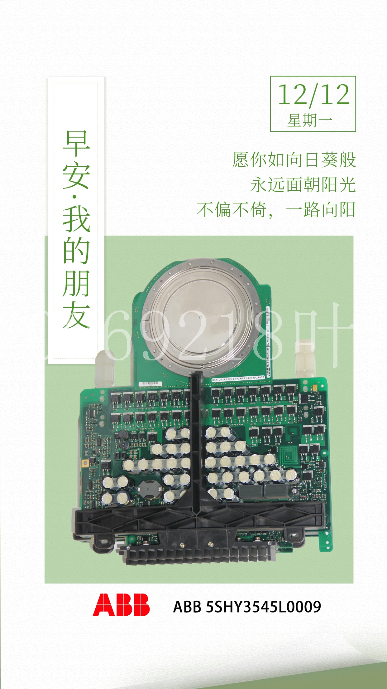
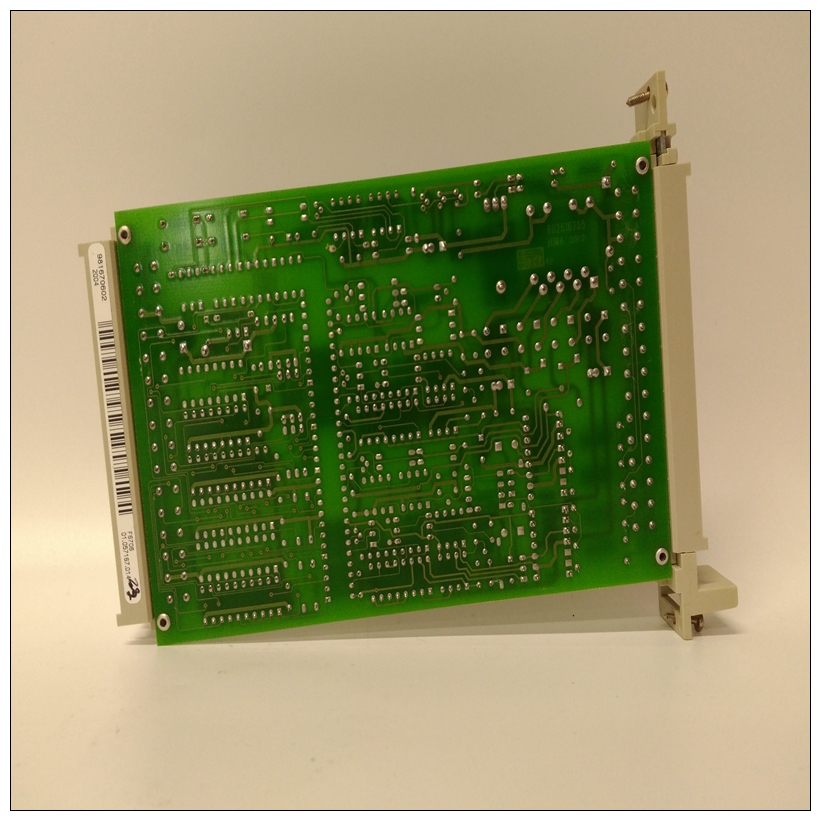
HIMA H51Q-HRS工控DCS系统备件
4.在以下位置查看数字输入和跳闸线圈监控的状态:A1 status×数字输入输入预期状态(开关打开)通过/未通过预期状态(关闭开关)通过/失败访问开路短路测试开路短路启动器状态开路短路紧急重启开路短路远程复位开路短路可分配输入1开路短路可指派输入2开路短路可指定输入3开路短路可分配输入4开路短路跳闸线圈监控无线圈GE Multilin 469电机管理继电器7-7 7测试7.2硬件功能测试7 7.2.7模拟输入和输出469模拟输入和模拟输出精度规格为满量程的±1%。执行以下步骤以验证准确性。用电压表验证模拟输入+24 V DC。a) 4-20毫安1。更改以下设置点:S12模拟输入/输出??模拟输入1?模拟输入1:“4-20 mA”S12模拟输出。电流表上的模拟输出值应为±0.2 mA。测量的模拟输入值应为±10单位。使用以下设置点强制模拟输出:S13 TESTING?TEST analog OUTPUT?Force analog outputs FUNCTION:“Enabled”S13 TESTING?TEST analog OUTPUT??analog OUTput1 FORCED VALUE:“0%”(以百分比为单位输入所需值;对模拟输出2至4重复)3。验证电流表读数以及测量的模拟输入读数。为了测试的目的,模拟输入由模拟输出输入(参见图7–1:设定点:S13 TESTING(测试)×TEST output(测试输出)继电器的强制操作:“R1跳闸”根据下表选择并存储值,验证操作R6服务继电器是否故障安全或正常通电,操作是否在每次测试前重置。在每次过载曲线测试之前,立即短接紧急重启终端,以确保使用的热容量为零。否则会缩短行程时间。注入适当振幅的电流,以获得所示值,并验证跳闸时间。电机负载可在:A2 METERING DATA(测量数据)电流测量3中查看。使用的热容量和预计跳闸时间可在以下内容中查看:A1状态电机状态平均相电流显示拾取电平预计跳闸时间公差范围测量跳闸时间1050 A 1.05从不适用1200 A 1.20 795.44秒779.53至811.35秒1750 A 1.75 169.66秒166.27至173.05秒3000 A 3.00 43.73秒42.86至44.60秒6000 A 6.00 9.99秒9.79至10.19秒。10000 A 10.00 5.55秒5.44至5.66秒7-10 469电机管理继电器GE Multilin 7.3附加功能测试7测试7 7.3.2功率测量测试无功和视在功率规格为Iavg<2×CT时×2×CT×VT×VT满量程的±1%。执行以下步骤以验证准确性。1.更改以下设置点:S2系统设置电流传感相位CT初级:“1000”S2系统设置电压传感VT连接类型:“Y型”S2系统安装电压传感电压互感器比率:“10.00:1”2。按照下表注入电流并施加电压。验证测量值的准确性。查看测量值:A2 METERING DATA??POWER METERING 7.3.3 UNBALANCE TEST 469测量负序电流(I2)与正序电流(I1)的比率。当电机负载超过FLA时,该值作为百分比用作不平衡水平。当平均相电流低于FLA,由于正序电流小得多,而负序电流保持相对恒定,因此降低不平衡值以防止误跳闸。降额公式为:序列电流,如图所示:(EQ 7.2)给定上图中的值,我们得到:(EQ7.3)如果FLA=1000,则:(EQ7.4),由于469不平衡量为:(EQ7.5)469不均衡量精度规格为±2%。执行以下步骤以验证准确性。1.更改以下设置点:S2系统设置电流传感相位CT主:“1000 A”S2系统设置电压传感×电机满载振幅FLA:“1000”2。注入下表所示的值,并验证测量值的准确性。在以下位置查看测量值:A2 METERING DATA(A2测量数据)电流测量注入电流预计不平衡水平测量不平衡水平1 A??系统相序:“ABC”S9电压元件??相位反转跳闸:“锁定”S9压力元件??相反转跳闸??分配跳闸继电器:“跳闸”2。按照下表施加电压。验证电压相位反转时的469操作。7.3.5短路测试469短路定时规格为+50 ms。拾取精度根据相电流输入。执行以下步骤以验证短路元件的性能。1.更改以下设置点:S2系统设置电流传感相位CT主:“1000”S
4. View the status of the digital inputs and trip coil supervision in: A1 STATUS Õ× DIGITAL INPUTS INPUT EXPECTED STATUS (SWITCH OPEN) PASS / FAIL EXPECTED STATUS (SWITCH CLOSED) PASS / FAIL ACCESS Open Shorted TEST Open Shorted STARTER STATUS Open Shorted EMERGENCY RESTART Open Shorted REMOTE RESET Open Shorted ASSIGNABLE INPUT 1 Open Shorted ASSIGNABLE INPUT 2 Open Shorted ASSIGNABLE INPUT 3 Open Shorted ASSIGNABLE INPUT 4 Open Shorted TRIP COIL SUPERVISION No Coil Coil GE Multilin 469 Motor Management Relay 7-7 7 TESTING 7.2 HARDWARE FUNCTIONAL TESTING 7 7.2.7 ANALOG INPUTS AND OUTPUTS The 469 specification for analog input and analog output accuracy is ±1% of full scale. Perform the steps below to verify accuracy. Verify the Analog Input +24 V DC with a voltmeter. a) 4-20 MA 1. Alter the following setpoints: S12 ANALOG I/O Õ× ANALOG INPUT1 Õ ANALOG INPUT1: “4-20 mA” S12 ANALOG I/O Õ× ANALOG INPUT1 Õ× ANALOG INPUT1 MINIMUM: “0” S12 ANALOG I/O Õ× ANALOG INPUT1 Õ× ANALOG INPUT1 MAXIMUM: “1000” (repeat this value for Analog Inputs 2 to 4) 2. Analog output values should be ±0.2 mA on the ammeter. Measured analog input values should be ±10 units. Force the analog outputs using the following setpoints: S13 TESTING Õ× TEST ANALOG OUTPUT Õ FORCE ANALOG OUTPUTS FUNCTION: “Enabled” S13 TESTING Õ× TEST ANALOG OUTPUT Õ× ANALOG OUTPUT 1 FORCED VALUE: “0%” (enter desired value in percent; repeat for Analog Outputs 2 through 4) 3. Verify the ammeter readings as well as the measured analog input readings. For the purposes of testing, the analog input is fed in from the analog output (see Figure 7–1: the setpoint: S13 TESTING Õ× TEST OUTPUT RELAYS Õ FORCE OPERATION OF RELAYS: “R1 Trip” select and store values as per the table below, verifying operation R6 Service relay is failsafe or energized normally, operating be reset prior to each test. Short the emergency restart terminals momentarily immediately prior to each overload curve test to ensure that the thermal capacity used is zero. Failure to do so will result in shorter trip times. Inject the current of the proper amplitude to obtain the values as shown and verify the trip times. Motor load may be viewed in: A2 METERING DATA Õ CURRENT METERING 3. Thermal capacity used and estimated time to trip may be viewed in: A1 STATUS Õ MOTOR STATUS AVERAGE PHASE CURRENT DISPLAYED PICKUP LEVEL EXPECTED TIME TO TRIP TOLERANCE RANGE MEASURED TIME TO TRIP 1050 A 1.05 never n/a 1200 A 1.20 795.44 sec. 779.53 to 811.35 sec. 1750 A 1.75 169.66 sec. 166.27 to 173.05 sec. 3000 A 3.00 43.73 sec. 42.86 to 44.60 sec. 6000 A 6.00 9.99 sec. 9.79 to 10.19 sec. 10000 A 10.00 5.55 sec. 5.44 to 5.66 sec. 7-10 469 Motor Management Relay GE Multilin 7.3 ADDITIONAL FUNCTIONAL TESTING 7 TESTING 7 7.3.2 POWER MEASUREMENT TEST The specification for reactive and apparent power is ±1% of ×2 × CT × VT × VT full scale at Iavg < 2 × CT. Perform the steps below to verify accuracy. 1. Alter the following setpoints: S2 SYSTEM SETUP Õ CURRENT SENSING Õ PHASE CT PRIMARY: “1000” S2 SYSTEM SETUP Õ× VOLTAGE SENSING Õ VT CONNECTION TYPE: “Wye” S2 SYSTEM SETUP Õ× VOLTAGE SENSING Õ× VOLTAGE TRANSFORMER RATIO: “10.00:1” 2. Inject current and apply voltage as per the table below. Verify accuracy of the measured values. View the measured values in: A2 METERING DATA Õ× POWER METERING 7.3.3 UNBALANCE TEST The 469 measures the ratio of negative sequence current (I2) to positive sequence current (I1). This value as a percent is used as the unbalance level when motor load exceeds FLA. When the average phase current is below FLA, the unbalance value is derated to prevent nuisance tripping as positive sequence current is much smaller and negative sequence current remains relatively constant. The derating formula is: sequence current as shown: (EQ 7.2) Given the values in the figure above, we have: (EQ 7.3) If FLA = 1000, then: (EQ 7.4) and since the 469 unbalance is: (EQ 7.5) The 469 specification for unbalance accuracy is ±2%. Perform the steps below to verify accuracy. 1. Alter the following setpoints: S2 SYSTEM SETUP Õ CURRENT SENSING Õ PHASE CT PRIMARY: “1000 A” S2 SYSTEM SETUP Õ CURRENT SENSING Õ× MOTOR FULL LOAD AMPS FLA: “1000 A” 2. Inject the values shown in the table below and verify accuracy of the measured values. View the measured values in: A2 METERING DATA Õ CURRENT METERING INJECTED CURRENT EXPECTED UNBALANCE LEVEL MEASURED UNBALANCE LEVEL 1 A Õ× SYSTEM PHASE SEQUENCE: “ABC” S9 VOLTAGE ELEMENTS Õ× PHASE REVERSAL Õ PHASE REVERSAL TRIP: “Latched” S9 VOLTAGE ELEMENTS Õ× PHASE REVERSAL Õ× ASSIGN TRIP RELAYS: “Trip” 2. Apply voltages as per the table below. Verify the 469 operation on voltage phase reversal. 7.3.5 SHORT CIRCUIT TEST The 469 specification for short circuit timing is +50 ms. The pickup accuracy is as per the phase current inputs. Perform the steps below to verify the performance of the short circuit element. 1. Alter the following setpoints: S2 SYSTEM SETUP Õ CURRENT SENSING Õ PHASE CT PRIMARY: “1000” S6 CURRENT ELEMENTS Õ SHORT CIRCUIT TRIP Õ SHORT CIRCUIT TRIP: “On” S6 CURRENT ELEMENTS Õ SHORT CIRCUIT TRIP Õ× ASSIGN TRIP RELAYS: “Trip” S6 CURRENT ELEMENTS Õ SHORT CIRCUIT TRIP Õ× SHORT CIRCUIT TRIP CONFIGURATION A.1.1 DESCRIPTION This appendix illustrates how two CTs may be used to sense three phase currents. The proper configuration for the use of two CTs rather than three to detect phase current is shown. Each of the two CTs acts as a current source. The current that comes out of the CT on phase A flows into the interposing CT on the relay marked A. From there, the current sums with the current that is flowing from the CT on phase C which has just passed through the interposing CT on the relay marked C. This ‘summed’ current flows through the interposing CT marked B and from there, the current splits up to return to its respective source (CT). Polarity is very important since the value of phase B must be the negative equivalent of A + C in order for the sum of all the vectors to equate to zero. Note that there is only one ground connection as shown. If two ground connections are made, a parallel path for current has been created. In the two CT configuration, the currents will sum vectorially at the common point of the two CTs. The diagram illustrates the two possible configurations. If one phase is reading high by a factor of 1.73 on a system that is known to be balanced, simply reverse the polarity of the leads at one of the two phase CTs (taking care that the CTs are still tied to ground at some point). Polarity is important. 808700A1.CDR A B C A B C :5 :5 :5 :COM :COM :COM 808702A1.CDR 1.73 1 1 1 1 60° 60° 60° A-2 469 Motor Management Relay GE Multilin A.1 TWO-PHASE CT CONFIGURATION APPENDIX A A To illustrate the point further, the following diagram shows how the current in phases A and C sum up to create phase ’B’. Once again, if the polarity of one of the phases is out by 180°, the magnitude of the resulting vector on a balanced system will be out by a factor of 1.73. On a three wire supply, this configuration will always work and unbalance will be detected properly. In the event of a single phase, there will always be a large unbalance present at the interposing CTs of the relay.


