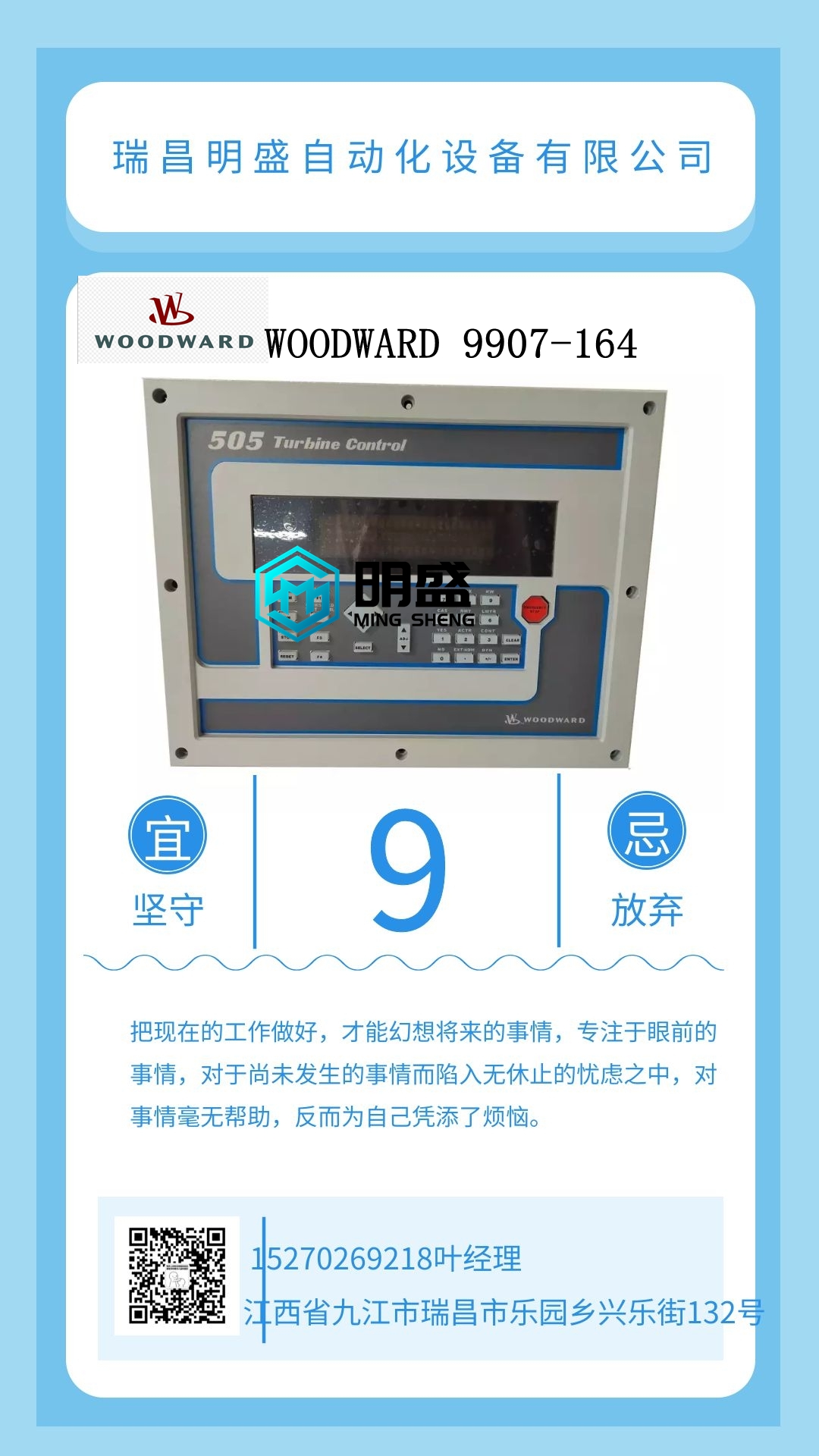
HIMA HSD8001工控模块系统备件,模块备件
可定义内存映射,允许计算机通过使用一个Modbus数据包读取多达124个非连续数据寄存器(设定值或实际值)。主计算机经常需要连续轮询每个连接的从属继电器中的各种值。如果这些值分散在整个内存映射中,那么读取它们将需要多次传输,并会给通信链路带来负担。用户可定义存储器映射可编程为将任何存储器映射地址连接到连续用户映射位置块中的一个,从而可以通过读取这些连续位置来访问它们。用户可定义区域有两个部分:1。包含125个实际值或设定点寄存器地址的寄存器索引区(存储器映射地址0180h至01FCh)。2.寄存器区域(存储器映射地址0100h至017Ch),其包含寄存器索引中的地址处的数据。在存储器映射的其余部分中分离的寄存器数据可以重新映射到用户可定义寄存器区域中的相邻寄存器地址。这是通过写入用户可定义的寄存器索引区域中的寄存器地址来实现的。这允许改进数据的吞吐量,并且可以消除对多个读取命令序列的需要。例如,如果需要从469中读取平均相电流(寄存器地址0306h)和热测试定子RTD温度(寄存器地址0320h)的值,则其地址可重新映射如下:1。使用功能代码06或16将0306h写入地址0180h(用户可定义寄存器索引0000)。2.使用功能代码06或16将0307h写入地址0181h(用户可定义寄存器索引0001)。(平均相电流为双寄存器数)3。使用功能代码06或16将0320h写入地址0182h(用户可定义寄存器索引0001)。寄存器0100h(用户定义寄存器0000)和0101h(用户可定义寄存器0001)的读取(功能代码03或04)将返回A相电流,寄存器0102h(用户可自定义寄存器0002)将返回热测试定子RTD温度。6.3.3事件记录器469事件记录器数据从地址3000h开始。地址3003h是指向感兴趣事件的指针(1表示最新事件,40表示最早事件)。要检索事件1,请将“1”写入事件记录选择器(3003h),并从3004h到3022h读取数据。要检索事件2,请将“2”写入事件记录选择器(3003h),并从3004h到3022h读取数据。可以以这种方式检索所有40个事件。每个事件的时间和日期戳可用于确保按顺序检索所有事件,而新事件不会破坏事件序列(事件1应比事件2更近,事件2应比事件3更近,等等)每次在跟踪缓冲区中发生跳闸时,A/D采样。跟踪缓冲区根据S1 PREFERENCES?跟踪内存缓冲区设置点进行分区。使用S1 PREFERENCES®Trace Memory Trigger(S1优先)设定值设置跟踪存储器触发器,这决定了存储了多少跳闸前和跳闸后循环。跟踪缓冲区带有时间和日期戳,并且可以与事件记录中的行程相关。当跳闸发生时,以这种方式捕获10个波形。这是3相电流、3个差分电流、接地电流和3个电压波形。该信息存储在易失性存储器中,如果继电器通电,该信息将丢失。要访问捕获的波形,请通过将其跟踪存储器通道(见下表)写入跟踪存储器通道选择器(地址30F1h)来选择感兴趣的波形。然后将跟踪存储器数据从地址3100h读取到3400h。每个周期有12个样本。读取的值以实际安培或伏特为单位。地址30F8h仅显示进入一个相位的数量,并验证测量值的准确性。查看测量值:A2 METERING DATA(测量数据)电流测量b)1 A INPUT(输入)1。用电压表改变以下电流5 A单位预期电流读数测量值V DC。执行以下步骤以验证数字输入的功能。1.打开所有数字输入和跳闸线圈监控电路的开关。2.查看数字输入和跳闸线圈监控的状态:实际值A1状态×数字输入3。关闭所有数字输入和跳闸线圈监控电路的开关。
Definable Memory Map, which allows a computer to read up to 124 nonconsecutive data registers (setpoints or actual values) by using one Modbus packet. It is often necessary for a master computer to continuously poll various values in each of the connected slave relays. If these values are scattered throughout the memory map, reading them would require numerous transmissions and would burden the communication link. The User Definable Memory Map can be programmed to join any memory map address to one in the block of consecutive User Map locations, so that they can be accessed by reading these consecutive locations. The User Definable area has two sections: 1. A register index area (memory map addresses 0180h to 01FCh) that contains 125 actual values or setpoints register addresses. 2. A register area (memory map addresses 0100h to 017Ch) that contains the data at the addresses in the register index. Register data that is separated in the rest of the memory map may be remapped to adjacent register addresses in the User Definable Registers area. This is accomplished by writing to register addresses in the User Definable Register Index area. This allows for improved through-put of data and can eliminate the need for multiple read command sequences. For example, if the values of Average Phase Current (register address 0306h) and Hottest Stator RTD Temperature (register address 0320h) are required to be read from an 469, their addresses may be remapped as follows: 1. Write 0306h to address 0180h (User Definable Register Index 0000) using function code 06 or 16. 2. Write 0307h to address 0181h (User Definable Register Index 0001) using function code 06 or 16. (Average Phase Current is a double register number) 3. Write 0320h to address 0182h (User Definable Register Index 0001) using function code 06 or 16. A read (function code 03 or 04) of registers 0100h (User Definable Register 0000) and 0101h (User Definable Register 0001) will return the Phase A Current and register 0102h (User Definable Register 0002) will return Hottest Stator RTD Temperature. 6.3.3 EVENT RECORDER The 469 event recorder data starts at address 3000h. Address 3003h is a pointer to the event of interest (1 representing the latest event and 40 representing the oldest event). To retrieve Event 1, write ‘1’ to the Event Record Selector (3003h) and read the data from 3004h to 3022h. To retrieve Event 2, write ‘2’ to the Event Record Selector (3003h) and read the data from 3004h to 3022h. All 40 events may be retrieved in this manner. The time and date stamp of each event may be used to ensure that all events have been retrieved in order without new events corrupting the sequence of events (Event 1 should be more recent than Event 2, Event 2 should be more recent than Event 3, etc.). NOTE GE Multilin 469 Motor Management Relay 6-11 6 COMMUNICATIONS 6.3 MEMORY MAP 6 6.3.4 WAVEFORM CAPTURE The 469 stores a number of cycles of A/D samples each time a trip occurs in a trace buffer. The trace buffer is partitioned according to the S1 PREFERENCES Õ× TRACE MEMORY BUFFERS setpoint. The Trace Memory Trigger is set up with the S1 PREFERENCES Õ× TRACE MEMORY TRIGGER setpoint and this determines how many pre-trip and post-trip cycles are stored. The trace buffer is time and date stamped and may be correlated to a trip in the event record. 10 waveforms are captured this way when a trip occurs. These are the 3 phase currents, 3 differential currents, ground current and 3 voltage waveforms. This information is stored in volatile memory and will be lost if power is cycled to the relay. To access the captured waveforms, select the waveform of interest by writing its trace memory channel (see following table) to the Trace Memory Channel Selector (address 30F1h). Then read the trace memory data from address 3100h to 3400h. There are 12 samples per cycle for each of the cycles. The values read are in actual amperes or volts. Address 30F8h shows the number of into one phase only and verify accuracy of the measured values. View the measured values in: A2 METERING DATA Õ CURRENT METERING b) 1 A INPUT 1. Alter the following CURRENT 5 A UNIT EXPECTED CURRENT READING MEASURED V DC with a voltmeter. Perform the steps below to verify functionality of the digital inputs. 1. Open switches of all of the digital inputs and the trip coil supervision circuit. 2. View the status of the digital inputs and trip coil supervision in: ACTUAL VALUES Õ A1 STATUS Õ× DIGITAL INPUTS 3. Close switches of all of the digital inputs and the trip coil supervision circuit.


