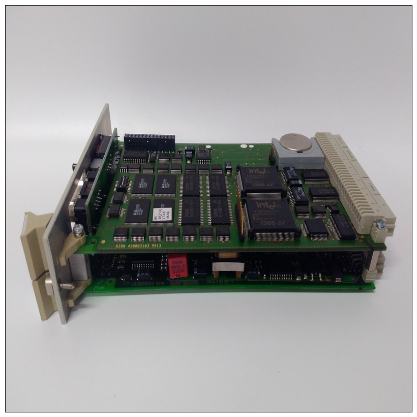
HIMA K9202B工控模块卡件,备件模块
执行操作Modbus实施:强制单线圈469实施:执行操作此功能代码允许主机请求469执行特定命令操作。存储器映射的命令区域中列出的命令编号对应于功能代码05的操作代码。操作命令也可以通过使用功能代码16写入存储器映射的命令区域来启动。有关完整的详细信息,请参阅第6-8页第6.2.8节:功能代码16:存储多个设置点。支持的操作:重置469(操作代码1);电机启动(操作代码2)电机停止(操作代码3);波形触发器(操作代码4)消息格式和示例:重置469(操作代码1)。6.2.5功能代码06:存储单个设定点Modbus实现:预设单个寄存器469实现:存储单个设置点此命令允许主机将单个设置点存储到469的存储器中。从属设备对该功能代码的响应是响应整个主传输。消息格式和示例:请求从设备11将值01F4存储在设定点地址1180中。在本示例中的传输完成后,设定点地址1180将包含值01F4。主传输:BYTES示例/描述从机11的从机地址1 0B消息功能代码1 05执行操作操作代码2 00 01重置命令(操作代码1)代码值2 FF 00执行功能CRC 2 DD 50主从机响应计算的CRC:BYTES示例/描述从属机11的从属机地址1 0B响应消息功能代码105执行操作操作代码2 00 01重置命令(操作代码1)代码值2 FF 00执行功能CRC 2 DD 50 CRC,由从属主传输计算:BYTES示例/描述从属11的从属地址1 0B消息功能代码1 06存储单个设置点数据起始地址2 11 80设置点地址1180数据2 01 F4数据,地址1180 CRC 2 8D A3 CRC,由主从属响应计算:字节示例/描述从机11功能代码1 06的从机地址1 0B响应消息存储单个设置点数据起始地址2 11 80设置点地址1180数据2 01 F4数据,地址1180 CRC 2 8D A3 CRC由从机GE Multilin 469电机管理继电器6-7 6通信6.2 MODBUS功能6 6.2.6功能代码07:读取设备状态MODBUS实现:读取异常状态469实施:读取设备状态这是一个用于快速读取所选设备状态的功能。短消息长度允许快速读取状态。根据从属设备的状态,返回的状态字节将具有设置为1或0的单个位。469一般状态字节:如果状态既没有停止也没有运行,则电机正在启动。消息格式和示例:从机11请求状态。6.2.7功能代码08:回路测试Modbus实施:回路测试469实施:回路试验此功能用于测试通信链路的完整性。469将响应请求。消息格式和示例:从机11的环回测试。位号描述位号。说明B0 R1跳闸继电器操作=1 B4 R5块启动继电器操作=B1 R2辅助继电器操作=B5 R6服务继电器操作=B2 R3辅助继电器操作=1 B6停止=1 B3 R4报警继电器操作=B7运行=1主传输:BYTES示例/描述从机11功能代码1 07读取设备状态CRC 2 47 42 CRC计算由主从机响应:BYTES示例/描述从机地址1 0B响应消息从机11功能代码1 07读取设备状态device status 1 59 status=01011001,二进制CRC 2 C2 08 CRC由从机主传输计算:BYTES示例/描述从属机地址1 0B消息从机功能代码1 08环回测试DIAG代码2 00 00必须为00 00数据2 00 00必须是00 00 CRC 2 E0 A1 CRC,由主从机响应计算:BYTES示例/描述从机地址1 0B响应消息,从机11功能代码1 08环回测试DIAG代码2 00 00必须是00 0数据2 00 00,从机6-8 469电机管理继电器GE Multilin 6.2 MODBUS功能6通信6 6.2.8功能代码16:存储MULTIPLE SETPOINTS Modbus实现:预设多个寄存器469实现:存储多个设定值此功能代码允许将多个设定点存储到469存储器中。Modbus“寄存器”是16位(两字节)值,先传输高位字节。因此,所有469个设定值都作为两字节值发送。一个传输中可存储的最大设定值数量取决于从设备。Modbus允许最多存储60个保持寄存器。对该功能代码的469响应是回显从属地址、功能代码、起始地址、存储的设置点的数量,
EXECUTE OPERATION Modbus Implementation: Force Single Coil 469 Implementation: Execute Operation This function code allows the master to request an 469 to perform specific command operations. The command numbers listed in the Commands area of the memory map correspond to operation code for function code 05. The operation commands can also be initiated by writing to the Commands area of the memory map using function code 16. Refer to Section 6.2.8: Function Code 16: Store Multiple Setpoints on page 6–8 for complete details. Supported Operations: Reset 469 (operation code 1); Motor Start (operation code 2) Motor Stop (operation code 3); Waveform Trigger (operation code 4) MESSAGE FORMAT AND EXAMPLE: Reset 469 (operation code 1). 6.2.5 FUNCTION CODE 06: STORE SINGLE SETPOINT Modbus Implementation: Preset Single Register 469 Implementation: Store Single Setpoint This command allows the master to store a single setpoint into the memory of an 469. The slave response to this function code is to echo the entire master transmission. MESSAGE FORMAT AND EXAMPLE: Request slave 11 to store the value 01F4 in Setpoint address 1180. After the transmission in this example is complete, setpoints address 1180 will contain the value 01F4. MASTER TRANSMISSION: BYTES EXAMPLE / DESCRIPTION SLAVE ADDRESS 1 0B message for slave 11 FUNCTION CODE 1 05 execute operation OPERATION CODE 2 00 01 reset command (operation code 1) CODE VALUE 2 FF 00 perform function CRC 2 DD 50 CRC calculated by the master SLAVE RESPONSE: BYTES EXAMPLE / DESCRIPTION SLAVE ADDRESS 1 0B response message from slave 11 FUNCTION CODE 1 05 execute operation OPERATION CODE 2 00 01 reset command (operation code 1) CODE VALUE 2 FF 00 perform function CRC 2 DD 50 CRC calculated by the slave MASTER TRANSMISSION: BYTES EXAMPLE / DESCRIPTION SLAVE ADDRESS 1 0B message for slave 11 FUNCTION CODE 1 06 store single setpoint DATA STARTING ADDRESS 2 11 80 setpoint address 1180 DATA 2 01 F4 data for address 1180 CRC 2 8D A3 CRC calculated by the master SLAVE RESPONSE: BYTES EXAMPLE / DESCRIPTION SLAVE ADDRESS 1 0B response message from slave 11 FUNCTION CODE 1 06 store single setpoint DATA STARTING ADDRESS 2 11 80 setpoint address 1180 DATA 2 01 F4 data for address 1180 CRC 2 8D A3 CRC calculated by the slave GE Multilin 469 Motor Management Relay 6-7 6 COMMUNICATIONS 6.2 MODBUS FUNCTIONS 6 6.2.6 FUNCTION CODE 07: READ DEVICE STATUS Modbus Implementation: Read Exception Status 469 Implementation: Read Device Status This is a function used to quickly read the status of a selected device. A short message length allows for rapid reading of status. The status byte returned will have individual bits set to 1 or 0 depending on the status of the slave device. 469 General Status Byte: If status is neither stopped or running, the motor is starting. MESSAGE FORMAT AND EXAMPLE: Request status from slave 11. 6.2.7 FUNCTION CODE 08: LOOPBACK TEST Modbus Implementation: Loopback Test 469 Implementation: Loopback Test This function is used to test the integrity of the communication link. The 469 will echo the request. MESSAGE FORMAT AND EXAMPLE: Loopback test from slave 11. Bit No. Description Bit No. Description B0 R1 Trip relay operated = 1 B4 R5 Block start relay operated = 1 B1 R2 Auxiliary relay operated = 1 B5 R6 Service relay operated = 1 B2 R3 Auxiliary relay operated = 1 B6 Stopped = 1 B3 R4 Alarm relay operated = 1 B7 Running = 1 MASTER TRANSMISSION: BYTES EXAMPLE / DESCRIPTION SLAVE ADDRESS 1 0B message for slave 11 FUNCTION CODE 1 07 read device status CRC 2 47 42 CRC calculated by the master SLAVE RESPONSE: BYTES EXAMPLE / DESCRIPTION SLAVE ADDRESS 1 0B response message from slave 11 FUNCTION CODE 1 07 read device status DEVICE STATUS 1 59 status = 01011001 in binary CRC 2 C2 08 CRC calculated by the slave MASTER TRANSMISSION: BYTES EXAMPLE / DESCRIPTION SLAVE ADDRESS 1 0B message for slave 11 FUNCTION CODE 1 08 loopback test DIAG CODE 2 00 00 must be 00 00 DATA 2 00 00 must be 00 00 CRC 2 E0 A1 CRC calculated by the master SLAVE RESPONSE: BYTES EXAMPLE / DESCRIPTION SLAVE ADDRESS 1 0B response message from slave 11 FUNCTION CODE 1 08 loopback test DIAG CODE 2 00 00 must be 00 00 DATA 2 00 00 must be 00 00 CRC 2 E0 A1 CRC calculated by the slave 6-8 469 Motor Management Relay GE Multilin 6.2 MODBUS FUNCTIONS 6 COMMUNICATIONS 6 6.2.8 FUNCTION CODE 16: STORE MULTIPLE SETPOINTS Modbus Implementation: Preset Multiple Registers 469 Implementation: Store Multiple Setpoints This function code allows multiple setpoints to be stored into the 469 memory. Modbus "registers" are 16-bit (two byte) values transmitted high order byte first. Thus all 469 setpoints are sent as two byte values. The maximum number of setpoints that can be stored in one transmission is dependent on the slave device. Modbus allows up to a maximum of 60 holding registers to be stored. The 469 response to this function code is to echo the slave address, function code, starting address, the number of Setpoints stored, and the CRC. MESSAGE FORMAT AND EXAMPLE: Request slave 11 to store the value 01F4 to Setpoint address 1180 and the value 01DE to setpoint address 1181.


