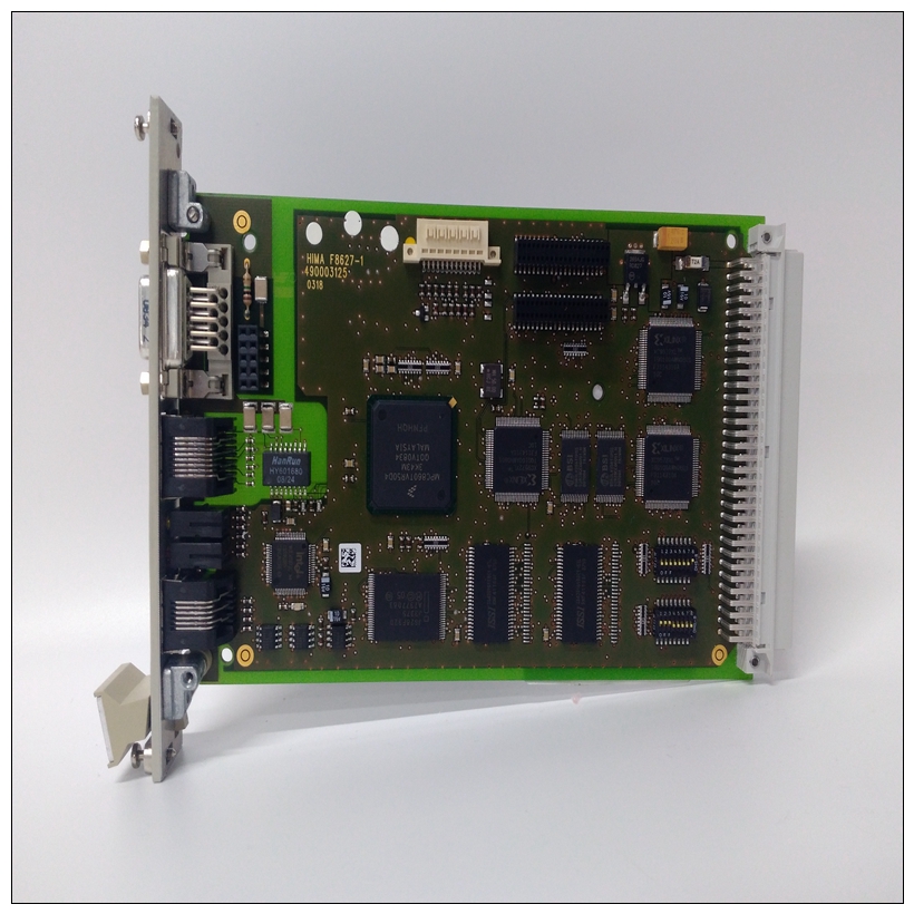
HIMA K9203备件模块,DCS工控模块备件
数字输入掩码的字节计数(一个字节)、指示所请求的数字输入状态的位掩码(一个或两个字节)和CRC(两字节)。注意:CRC以两字节数字的形式发送,先发送低位字节。示例1:请求从属设备11响应数字输入5至9的状态:示例2:请求从属11响应数字输出1至4的状态:数字输入状态数字输入状态D1:访问关闭D7:可分配输入2关闭D2:测试打开D8:可指定输入3关闭D3:启动器状态打开D9:可指派输入4关闭D4:紧急重启打开位掩码(LSB)0111 0001 D5:远程重置闭合位掩码(MSB)0000 0001 D6:可分配输入1闭合主传输:BYTES示例/描述从机11功能代码1 02读取数字输入状态STARTING digital Input 2 00 05从数字输入5 NUMBER OF DIGITAAL Input 2 0 05 5数字输入(即D5、D6、D7、D8、D9)CRC 2 A8 A2 CRC,由主从机计算响应:字节示例/描述从机11的从机地址1 0B响应消息功能代码1 02读取继电器线圈状态字节计数1 02 2字节位掩码位掩码2 71 01请求数字输入CRC的位掩码2 C5 B9 CRC由从机数字输入状态数字输入状态D1计算:访问关闭D6:可分配输入1关闭D2:测试打开D7:可指定输入2关闭D3:启动器状态打开D8:可分配输入3打开D4:紧急重启打开D9:可指定输入4关闭D5:远程重置闭合位掩码(LSB)0111 0001主传输:BYTES示例/描述从机11功能代码1 02的从机地址1 0B消息读取数字输入状态从数字输入1数字输入数量2 00 04 4数字输入开始启动数字输入2 00 01(即D1、D2、D3、D4)CRC 2 28 A3由主从机响应计算的CRC:BYTES示例/描述从机11功能代码1 02读取继电器线圈状态BYTE COUNT 1 01 2字节位掩码位掩码2所请求数字输入的01位掩码CRC 2 63 90由从机GE Multilin 469电机管理继电器6-5 6通信6.2 MODBUS计算的CRC功能6 6.2.3功能代码03/04:读取设定值/实际值Modbus实现:读取输入和保持寄存器469实现:读取设定点和实际值对于Modbus的469实现,这些命令可用于读取任何设定值(“保持寄存器”)或实际值(“输入寄存器”)。保持寄存器和输入寄存器是16位(两字节)值,先以高位字节传输。因此,所有469个设定值和实际值都作为两个字节发送。一次传输中可读取的最大寄存器数为125。功能代码03和04被配置为可互换地读取设定值或实际值,因为某些PLC不支持这两个功能代码。从机对这些功能码的响应是从机地址、功能码、后续数据字节数的计数、数据本身和CRC。每个数据项都以两字节的形式发送,首先发送高阶字节。CRC以两字节数的形式发送,低位字节先发送。消息格式和示例:请求从机11以地址0308开始的2个寄存器进行响应。在本例中,这些地址中的寄存器数据为:地址数据0308 0064 0309 000A主传输:BYTES示例/描述从站地址1 0B消息从站11功能代码1 03读取寄存器数据起始地址2 03 08数据起始于0308设置点数量2 00 02 2个寄存器(共4字节)CRC 2 45 27 CRC,由主从站响应计算:BYTES示例/描述从机11的从机地址1 0B响应消息功能代码1 03读取寄存器字节计数1 04 2寄存器=地址0308中的4字节数据1 2 00 64值数据2 00 0A地址0309中的值CRC 2 EB 91 CRC由从机6-6 469电机管理继电器GE Multilin 6.2 MODBUS功能6通信6 6.2.4功能代码05计算:
byte count of digital input mask (one byte), bit mask indicating the status of requested digital inputs (one or two bytes), and CRC (two bytes). Note: the CRC is sent as a two byte number with the low order byte sent first. Example 1: Request slave 11 to respond with status of digital inputs 5 to 9: Example 2: Request slave 11 to respond with status of digital inputs 1 to 4: Digital Input Status Digital Input Status D1: Access Closed D7: Assignable Input 2 Closed D2: Test Open D8: Assignable Input 3 Closed D3: Starter Status Open D9: Assignable Input 4 Closed D4: Emergency Restart Open Bit Mask (LSB) 0111 0001 D5: Remote Reset Closed Bit Mask (MSB) 0000 0001 D6: Assignable Input 1 Closed MASTER TRANSMISSION: BYTES EXAMPLE / DESCRIPTION SLAVE ADDRESS 1 0B message for slave 11 FUNCTION CODE 1 02 read digital input status STARTING DIGITAL INPUT 2 00 05 starting at digital input 5 NUMBER OF DIGITAL INPUTS 2 00 05 5 digital inputs (i.e. D5, D6, D7, D8, D9) CRC 2 A8 A2 CRC calculated by the master SLAVE RESPONSE: BYTES EXAMPLE / DESCRIPTION SLAVE ADDRESS 1 0B response message from slave 11 FUNCTION CODE 1 02 read relay coil status BYTE COUNT 1 02 2 byte bit mask BIT MASK 2 71 01 bit mask of requested digital input CRC 2 C5 B9 CRC calculated by the slave Digital Input Status Digital Input Status D1: Access Closed D6: Assignable Input 1 Closed D2: Test Open D7: Assignable Input 2 Closed D3: Starter Status Open D8: Assignable Input 3 Open D4: Emergency Restart Open D9: Assignable Input 4 Closed D5: Remote Reset Closed Bit Mask (LSB) 0111 0001 MASTER TRANSMISSION: BYTES EXAMPLE / DESCRIPTION SLAVE ADDRESS 1 0B message for slave 11 FUNCTION CODE 1 02 read digital input status STARTING DIGITAL INPUT 2 00 01 starting at digital input 1 NUMBER OF DIGITAL INPUTS 2 00 04 4 digital inputs (i.e. D1, D2, D3, D4) CRC 2 28 A3 CRC calculated by the master SLAVE RESPONSE: BYTES EXAMPLE / DESCRIPTION SLAVE ADDRESS 1 0B response message from slave 11 FUNCTION CODE 1 02 read relay coil status BYTE COUNT 1 01 2 byte bit mask BIT MASK 2 01 bit mask of requested digital input CRC 2 63 90 CRC calculated by the slave GE Multilin 469 Motor Management Relay 6-5 6 COMMUNICATIONS 6.2 MODBUS FUNCTIONS 6 6.2.3 FUNCTION CODES 03/04: READ SETPOINTS / ACTUAL VALUES Modbus implementation: Read Input and Holding Registers 469 Implementation: Read Setpoints and Actual Values For the 469 implementation of Modbus, these commands can be used to read any Setpoint ("holding registers") or Actual Value ("input registers"). Holding and input registers are 16 bit (two byte) values transmitted high order byte first. Thus all 469 Setpoints and Actual Values are sent as two bytes. The maximum number of registers that can be read in one transmission is 125. Function codes 03 and 04 are configured to read setpoints or actual values interchangeably because some PLCs do not support both function codes. The slave response to these function codes is the slave address, function code, a count of the number of data bytes to follow, the data itself and the CRC. Each data item is sent as a two byte number with the high order byte sent first. The CRC is sent as a two byte number with the low order byte sent first. MESSAGE FORMAT AND EXAMPLE: Request slave 11 to respond with 2 registers starting at address 0308. For this example the register data in these addresses is: Address Data 0308 0064 0309 000A MASTER TRANSMISSION: BYTES EXAMPLE / DESCRIPTION SLAVE ADDRESS 1 0B message for slave 11 FUNCTION CODE 1 03 read registers DATA STARTING ADDRESS 2 03 08 data starting at 0308 NUMBER OF SETPOINTS 2 00 02 2 registers (4 bytes total) CRC 2 45 27 CRC calculated by the master SLAVE RESPONSE: BYTES EXAMPLE / DESCRIPTION SLAVE ADDRESS 1 0B response message from slave 11 FUNCTION CODE 1 03 read registers BYTE COUNT 1 04 2 registers = 4 bytes DATA 1 2 00 64 value in address 0308 DATA 2 2 00 0A value in address 0309 CRC 2 EB 91 CRC calculated by the slave 6-6 469 Motor Management Relay GE Multilin 6.2 MODBUS FUNCTIONS 6 COMMUNICATIONS 6 6.2.4 FUNCTION CODE 05:


