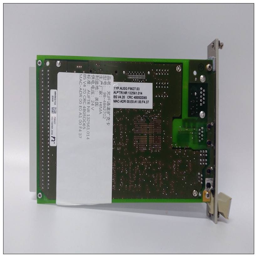
HIMA XPSMF2DO1602模拟量输入模块
反向shr(x)右移运算符(x的LSbit被移位到定时约束中。接收设备必须测量字符接收之间的时间。如果三个半字符时间过去了,没有新字符或数据包完成,则必须重置通信链路(即所有从设备开始侦听来自主设备的新传输)。因此,在9600波特时,大于3.5×1/9600×10=3.65 ms的延迟将导致通信链路复位。GE Multilin 469电机管理继电器6-3 6通信6.2 MODBUS功能6 6.2MODBUS功能6.2.1支持的功能469支持以下功能:MODBUS功能代码01:读取继电器线圈MODBUS功能代码02:读取数字输入状态MODBUS功能代码03:读取设定点和实际值MODBUS功能代码04:读取设定点和实际值功能代码05:执行操作Modbus功能代码06:存储单设定点Modbus功能代码07:读取设备状态Modbus功能代码08:环回测试Modbus功能代码16:存储多个设定点6.2.2功能代码01/02:读取继电器线圈/数字输入状态Modbus实现:读取线圈和输入状态469实现:读取这些命令可用于读取继电器线圈状态或数字输入状态。消息格式和示例,功能01:标准实现需要以下内容:从地址(一个字节)、功能代码(一个)、启动继电器线圈(两个字节),要读取的线圈数(两个)和CRC(两个字符)。从机响应包括从机地址(一个字节)、功能代码(一个)、继电器线圈掩码字节计数(一字节;由于只有六个继电器线圈,所以始终为01)、指示请求的继电器线圈状态的位掩码(一个字节)和CRC(两个字节)。请求从机11响应继电器线圈3至5的状态:如果输入了零的启动继电器线圈(启动数字输入),469将默认为一。如果请求的继电器数量(数字输入数量)超过可用的继电器数量,系统将提示用户非法数据信息。继电器状态R1通电R2断电R3断电R4断电R5通电R6通电位掩码0011 0001(0 x 31)主传输:BYTES示例/描述从属11功能代码1 01的从属地址1 0B消息读取继电器线圈状态启动继电器线圈2 00 03启动继电器线圈3继电器数量2 00 03 3个继电器线圈(即R3、R4、R5)CRC 2 8C A1 CRC,通过主从机响应:BYTES示例/描述从机11功能代码1 01读取继电器线圈状态BYTE COUNT 1 01 1字节位掩码位掩码1请求继电器的10位掩码(0001 0000)CRC 2 53 93 CRC由从机计算注释6-4 469电机管理继电器GE Multilin 6.2 MODBUS FUNCTIONS 6 COMMUNICATIONS 6 message FORMAT AND示例,功能02:标准实现需要以下内容:从属地址(一个字节)、功能代码(一字节)、起始数字输入(两字节)、要读取的数字输入数量(两个字节)和CRC(两个)。从属响应是从属地址(一个字节)、功能代码(一个字符)、地址和地址,
reversed shr (x) right shift operator (the LSbit of x is shifted into a timing constraints. The receiving device must measure the time between the reception of characters. If three and one half character times elapse without a new character or completion of the packet, then the communication link must be reset (i.e. all slaves start listening for a new transmission from the master). Thus at 9600 baud a delay of greater than 3.5 × 1 / 9600 × 10 = 3.65 ms will cause the communication link to be reset. GE Multilin 469 Motor Management Relay 6-3 6 COMMUNICATIONS 6.2 MODBUS FUNCTIONS 6 6.2MODBUS FUNCTIONS 6.2.1 SUPPORTED FUNCTIONS The following functions are supported by the 469: Modbus Function Code 01: Read Relay Coil Modbus Function Code 02: Read Digital Input Status Modbus Function Code 03: Read Setpoints and Actual Values Modbus Function Code 04: Read Setpoints and Actual Values Modbus Function Code 05: Execute Operation Modbus Function Code 06: Store Single Setpoint Modbus Function Code 07: Read Device Status Modbus Function Code 08: Loopback Test Modbus Function Code 16: Store Multiple Setpoints 6.2.2 FUNCTION CODES 01/02: READ RELAY COIL / DIGITAL INPUT STATUS Modbus implementation: Read Coil and Input Status 469 Implementation: Read Relay Coil and Digital Input Status For the 469 implementation of Modbus, these commands can be used to read Relay Coil Status or Digital Input Status. MESSAGE FORMAT AND EXAMPLE, FUNCTION 01: The standard implementation requires the following: slave address (one byte), function code (one byte), starting relay coil (two bytes), number of coils to read (two bytes), and CRC (two bytes). The slave response is the slave address (one byte), function code (one byte), relay coil mask byte count (one byte; always 01 since only six relay coils), bit mask indicating the status of requested relay coils (one byte), and CRC (two bytes). Request slave 11 to respond with status of relay coil 3 to 5: If a Starting Relay Coil (Starting Digital Input) of Zero is entered, the 469 will default it to One. If the Number of Relays (Number of Digital Inputs) requested exceeds the number of relays available, the user is prompted with a ILLEGAL DATA message. Relay Status R1 Energized R2 De-energized R3 De-energized R4 De-energized R5 Energized R6 Energized Bit Mask 0011 0001 (0 x 31) MASTER TRANSMISSION: BYTES EXAMPLE / DESCRIPTION SLAVE ADDRESS 1 0B message for slave 11 FUNCTION CODE 1 01 read relay coil status STARTING RELAY COIL 2 00 03 starting relay coil 3 NUMBER OF RELYAS 2 00 03 3 relays coils (i.e. R3, R4, R5) CRC 2 8C A1 CRC calculated by the master SLAVE RESPONSE: BYTES EXAMPLE / DESCRIPTION SLAVE ADDRESS 1 0B response message from slave 11 FUNCTION CODE 1 01 read relay coil status BYTE COUNT 1 01 1 byte bit mask BIT MASK 1 10 bit mask of requested relay (0001 0000) CRC 2 53 93 CRC calculated by the slave NOTE 6-4 469 Motor Management Relay GE Multilin 6.2 MODBUS FUNCTIONS 6 COMMUNICATIONS 6 MESSAGE FORMAT AND EXAMPLE, FUNCTION 02: The standard implementation requires the following: slave address (one byte), function code (one byte), starting digital input (two byte), number of digital inputs to read (two bytes), and CRC (two bytes). The slave response is the slave address (one byte), function code (one byte),


