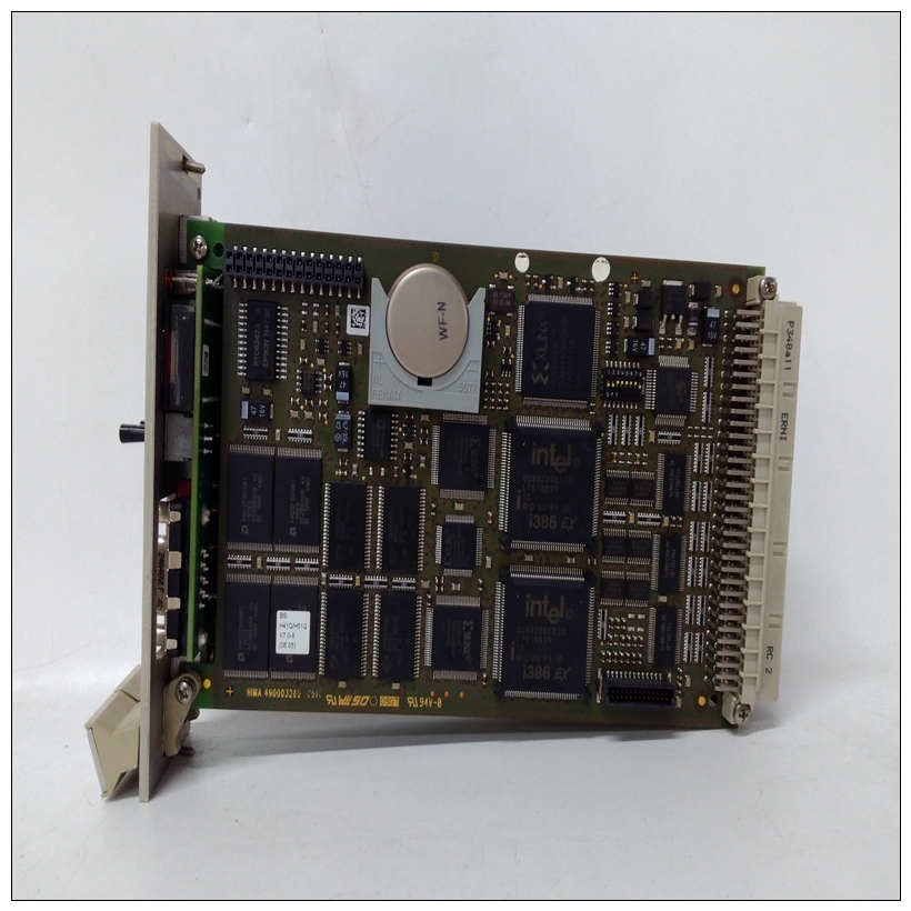
HIMA Z6013机器人模块,控制模块
功能切换到两个不同的开关时,将显示此消息。•输入无效服务代码:如果在S13 469测试中输入了无效代码,则显示此消息此处按下的键无效:在某些情况下,某些键没有功能(例如,查看实际值时的任何数字键)。如果在没有功能的地方按下按键,将显示此消息。•数据清除成功:此消息确认S1 469 SETUP?清除数据或S1 469设置?安装设置点组中的数据已清除或重置。•页面顶部:此消息将指示何时到达页面顶部。•页面底部:此消息将指示何时到达页面底部。•列表顶部:此消息将指示何时到达子组顶部。•列表底部:此消息将指示何时到达子组的底部。输入输入重置重置输入输入输入输入5-28 469电机管理继电器GE Multilin 5.8诊断5实际值5•[.]键用于推进光标:任何时候查看需要文本编辑的设置点,都会立即显示此消息,提示用户使用十进制键进行光标控制。如果设置点在一(1)分钟内未更改,则消息将再次闪烁。•NO ALARMS(无警报):当没有激活警报时,如果试图进入A1 STATUS(A1状态)ALARM STATUS(警报状态)子组,则显示此消息。•NO START BLOCKS ACTIVE(无启动块激活):当没有激活的启动块时,如果试图进入A1 STATUS?启动块子组,则显示此消息。•此功能未编程:如果试图输入实际值消息子组,当未为该功能配置设定点时,将显示此消息。GE Multilin 469电机管理继电器6-1 6通信6.1 MODBUS协议6 6通信6.1 MODBUS协议6.1.1电气接口硬件或电气接口为以下之一:来自后端子连接器的两个2线RS485端口之一,或来自前面板连接器的RS232。在2线RS485链路中,数据流是双向的。RS485和RS232端口的数据流均为半双工。也就是说,数据从不同时发送和接收。RS485线路应以菊花链配置(避免星形连接)与安装在链路两端的终端网络连接,即主端和离主端最远的从端。终端网络应由120Ω 当与Belden 9841 RS485电线一起使用时,电阻器与1nF陶瓷电容器串联。端接电阻器的值应等于线路的特性阻抗。大约为120Ω 用于标准#22AWG双绞线。应始终使用屏蔽线以尽量减少噪声。极性在RS485通信中很重要。每个469的每个“+”端子必须连接在一起,系统才能运行。有关正确串行端口接线的详细信息,请参阅第2-18页第2.2.11节:RS485通信端口。6.1.2 MODBUS RTU协议469实施了AEG Modicon MODBUS RTU串行通信标准的一个子集。许多流行的可编程控制器通过允许继电器直接连接的适当接口卡直接支持该协议。尽管Modbus协议与硬件无关,但469个接口包括两个2线RS485端口和一个RS232端口。Modbus是一个单主多从协议,适用于RS485硬件提供的多点配置。在这种配置中,在单个通信信道上最多可以将32个从设备菊花链在一起。469永远是奴隶。不能将其编程为主机。计算机或PLC通常被编程为主机。Modbus协议有两种版本:远程终端单元(RTU,二进制)和ASCII。
function to two different switches, this message will appear. • INVALID SERVICE CODE ENTERED: This message appears if an invalid code is entered in S13 469 TESTING Õ× MULTILIN USE ONLY. • KEY PRESSED HERE IS INVALID: Under certain situations, certain keys have no function (e.g. any number key while viewing Actual Values). If a key is pressed where it should have no function, this message will appear. • DATA CLEARED SUCCESSFULLY: This message confirms that data has been cleared or reset in the S1 469 SETUP Õ× CLEAR DATA or S1 469 SETUP Õ× INSTALLATION setpoint groups. • TOP OF PAGE: This message will indicate when the top of a page has been reached. • BOTTOM OF PAGE: This message will indicate when the bottom of a page has been reached. • TOP OF LIST: This message will indicate when the top of subgroup has been reached. • BOTTOM OF LIST: This message will indicate when the bottom of a subgroup has been reached. ENTER ENTER RESET RESET RESET ENTER ENTER ENTER ENTER ENTER ENTER 5-28 469 Motor Management Relay GE Multilin 5.8 DIAGNOSTICS 5 ACTUAL VALUES 5 • [.] KEY IS USED TO ADVANCE THE CURSOR: Any time a setpoint that requires text editing is viewed, this message will appear immediately to prompt the user to use the decimal key for cursor control. If the setpoint is not altered for one (1) minute, the message will flash again. • NO ALARMS: This message appears if an attempt is made to enter the A1 STATUS Õ ALARM STATUS subgroup when there are no active alarms. • NO START BLOCKS ACTIVE: This message appears if an attempt is made to enter the A1 STATUS Õ× START BLOCKS subgroup when there are no active Start Blocks. • THIS FEATURE NOT PROGRAMMED: If an attempt is made to enter an actual value message subgroup, when the setpoints are not configured for that feature, this message will appear. GE Multilin 469 Motor Management Relay 6-1 6 COMMUNICATIONS 6.1 MODBUS PROTOCOL 6 6 COMMUNICATIONS 6.1MODBUS PROTOCOL 6.1.1 ELECTRICAL INTERFACE The hardware or electrical interface is one of the following: one of two 2-wire RS485 ports from the rear terminal connector or the RS232 from the front panel connector. In a 2-wire RS485 link, data flow is bidirectional. Data flow is half duplex for both the RS485 and the RS232 ports. That is, data is never transmitted and received at the same time. RS485 lines should be connected in a daisy chain configuration (avoid star connections) with a terminating network installed at each end of the link, i.e. at the master end and at the slave farthest from the master. The terminating network should consist of a 120 Ω resistor in series with a 1 nF ceramic capacitor when used with Belden 9841 RS485 wire. The value of the terminating resistors should be equal to the characteristic impedance of the line. This is approximately 120 Ω for standard #22 AWG twisted pair wire. Shielded wire should always be used to minimize noise. Polarity is important in RS485 communications. Each ’+’ terminal of every 469 must be connected together for the system to operate. See Section 2.2.11: RS485 Communications Ports on page 2–18 for details on correct serial port wiring. 6.1.2 MODBUS RTU PROTOCOL The 469 implements a subset of the AEG Modicon Modbus RTU serial communication standard. Many popular programmable controllers support this protocol directly with a suitable interface card allowing direct connection of relays. Although the Modbus protocol is hardware independent, the 469 interfaces include two 2-wire RS485 ports and one RS232 port. Modbus is a single master, multiple slave protocol suitable for a multi-drop configuration as provided by RS485 hardware. In this configuration up to 32 slaves can be daisy-chained together on a single communication channel. The 469 is always a slave. It cannot be programmed as a master. Computers or PLCs are commonly programmed as masters. The Modbus protocol exists in two versions: Remote Terminal Unit (RTU, binary) and ASCII.


