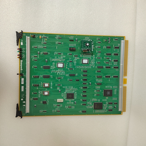
HONEYWELL 51306511-175B CC-PAIN01机器人卡件,工业卡件
。这可能是起动机维护的有用信息。当计数器达到50000时,该计数器将重置为0。该信息可通过S1 469 SETUP(设置)×INSTALLATION(安装)×RESET STARTER information(重置启动器信息)设定点清除。如果其中一个可分配的数字输入被编程为数字计数器,则计数器测量值将显示在此处。如果计数器为递增类型或使用S1 469 SETUP(设置)×CLEAR DATA(清除数据)×PRESET DIGITAL counter(预设数字计数器)设定值预设为预定值,则计数器可重置为零。功率因数跳闸:0范围:0至50000无功功率跳闸:0量程:0至五万反向功率跳闸:1范围:0到50000欠功率跳闸:2范围:0~50000模拟I/P 1跳闸:0幅度:0到五万。消息反映模拟输入名称/单位为编程的模拟I/P 2跳闸:0范围:使用S1 469 SETUP(设置)×INSTALLATION(安装)×RESET MOTOR INFORMATION(重置电机信息)设置点清除。可以在此处查看“开始之间的时间计时器”值。该值可能有助于计划电机停机。这里还可以查看STARTS/HOUR TIMER值。n计时器n[输入]更多电机运行时间:0小时范围:0到100000小时。启动时间间隔计时器:0分钟范围:0至500分钟。启动/小时计时器0 0 0 0分钟范围0到60分钟。输入退出消息退出消息退出5-22 469电机管理继电器GE Multilin 5.6 A5事件记录器5实际值5 5.6A5事件记录器5.6.1事件01到事件40路径:实际值×A5事件记录器[ENTER]事件01(40)n[ENTER]EVENT 01无事件事件01时间:00:00:00.0范围:小时:分钟:秒事件01日期:1992年1月1日范围:月日,年份EVENT01期间电机转速:低速范围:高速,低速仅在启用双速功能的情况下可见。EVENT01:0 RPM范围:0至3600 RPM。仅当数字输入编程为转速表a:0 B:0 C:0 a EVENT01范围:0到100000 a电机负载EVENT01:0.00 x FLA范围:0.00到20.00 x FLA电流不平衡EVENT01:0%范围:0至100%接地电流EVENT01=0.00 a范围:0.00至5000.0 a a:0 B:0 C:0 C:0 a Diff.EV01范围:1到5000 a时才可见。仅当相位差CT设置为HOTTEST STATOR RTD:0°C EVENT01范围:-50至250°C时才可见,----(无RTD)。仅当至少一个RTD设置为定子热测试轴承RTD:0°C EVENT01范围:-50至250°C时才可见,----(无RTD)。仅当至少一个RTD设置为轴承热测试其他RTD:0°C EVENT01范围:-50至250°C时才可见,----(无RTD)。仅当至少一个RTD设置为“其他环境RTD:0°C EVENT01范围:-50至250°C,----(无RTD)”时才可见。仅当至少一个RTD设置为环境Vab:0 Vbc:0 Vca:0 A EVENT01范围:0至20000 A时可见。仅当VT连接设置为None Van:0 Vbn:0 Vcn:0 A VENNT01范围为0至20000 A.仅当VT接头编程为Y型系统频率EVENT01:0.00 Hz范围:0.00,20.00至120.00 Hz 0 kW 0 kVA 0 kvar EVENT01量程:–50000至50000 kVA时可见。仅当VT连接设置为无功率因数事件01时可见:0.00范围:0.01至0.99超前或滞后,0.00,1.00仅当VT相连时可见。事件包括所有跳闸、可选的任何警报(服务警报和469未插入警报除外,这些警报始终记录为事件)、控制电源损失、控制电源的应用、紧急重启以及阻塞功能激活时电机启动。如果模块启动触点短路以绕过469并启动电机,则可能发生后一种事件。事件01是最近的事件,事件40是最早的事件。每一个新事件都会使另一个事件记录上升一个,直到到达事件40。当新事件发生时,事件40中的事件记录丢失。可使用S1 469 SETUP(设置)×CLEAR DATA(清除数据)×CLER EVENT RECORD(清除事件记录)设定点清除该信息。模拟I/P 2事件01:0单位范围:–50000至50000模拟I/P 3事件01:1单位范围:-5万至50000模拟/P 4事件01:2单位范围:-5000至50000表5–3:事件原因跳闸加速跳闸环境RTD12跳闸模拟I/P 1至4跳闸轴承RTD 7跳闸轴承RTD 8跳闸轴承RTD 9跳闸轴承RTD 10跳闸电流U/B跳闸差动跳闸一般开关A跳闸一般开关B跳闸一般开关C跳闸一般开关D跳闸接地故障备用接地故障跳闸不完整顺序跳闸甩负荷跳闸机械堵塞跳闸过载跳闸过压跳闸相位反转跳闸功率因数跳闸压力开关。跳闸无功功率跳闸远程跳闸RTD11跳闸短路备用短路跳闸单相(不平衡)速度开关跳闸定子RTD 1跳闸定子RTD 2跳闸定子RTD 3跳闸定子RTD 4跳闸定子RTD 5跳闸定子RTD 6跳闸转速计跳闸欠电流跳闸欠电压跳闸振动开关跳闸电压。频率跳闸警报(可选事件)环境RTD12报警模拟I/P 1至4报警轴承RTD 7报警轴承RTD 8报警轴承RTD 9报警轴承RTD 10报警断路器故障计数器报警电流需求报警电流U/B报警通用开关A报警通用开关B报警通用开关C报警通用开关。
. This may be useful information for starter maintenance. When the counter reaches 50000, that counter will reset to 0. This information may be cleared with the S1 469 SETUP Õ× INSTALLATION Õ× RESET STARTER INFORMATION setpoint. If one of the assignable digital inputs is programmed as Digital Counter, that counter measurement will appear here. The counter can be reset to zero if the counter is of the incrementing type or pre-set to a predetermined value using the S1 469 SETUP Õ× CLEAR DATA Õ× PRESET DIGITAL COUNTER setpoint. POWER FACTOR TRIPS: 0 Range: 0 to 50000 REACTIVE POWER TRIPS: 0 Range: 0 to 50000 REVERSE POWER TRIPS: 0 Range: 0 to 50000 UNDERPOWER TRIPS: 0 Range: 0 to 50000 ANALOG I/P 1 TRIPS: 0 Range: 0 to 50000. Message reflects Analog Input Name/units as programmed ANALOG I/P 2 TRIPS: 0 Range: cleared using the S1 469 SETUP Õ× INSTALLATION Õ× RESET MOTOR INFORMATION setpoint. The TIME BETWEEN STARTS TIMER value may be viewed here. This value might be useful for planning a motor shutdown. The STARTS/HOUR TIMER value is also viewable here. n TIMERS n [ENTER] for more MOTOR RUNNING HOURS: 0 hr Range: 0 to 100000 hrs. TIME BETWEEN STARTS TIMER: 0 min Range: 0 to 500 min. STARTS/HOUR TIMERS 0 0 0 0 0 min Range: 0 to 60 min. ENTER ESCAPE ð ð MESSAGE ESCAPE MESSAGE ESCAPE 5-22 469 Motor Management Relay GE Multilin 5.6 A5 EVENT RECORDER 5 ACTUAL VALUES 5 5.6A5 EVENT RECORDER 5.6.1 EVENT 01 TO EVENT 40 PATH: ACTUAL VALUES Õ× A5 EVENT RECORDER Õ [ENTER] EVENT 01(40) n [ENTER] EVENT 01 No Event TIME OF EVENT 01: 00:00:00.0 Range: hour:minutes:seconds DATE OF EVENT 01: Jan. 01, 1992 Range: month day, year MOTOR SPEED DURING EVENT01: Low Speed Range: High Speed, Low Speed Seen only if the Two-Speed feature is enabled TACHOMETER DURING EVENT01: 0 RPM Range: 0 to 3600 RPM. Seen only if a Digital Input is programmed as Tachometer A: 0 B: 0 C: 0 A EVENT01 Range: 0 to 100000 A MOTOR LOAD EVENT01: 0.00 x FLA Range: 0.00 to 20.00 x FLA CURRENT UNBALANCE EVENT01: 0% Range: 0 to 100% GROUND CURRENT EVENT01: 0.00 A Range: 0.00 to 5000.0 A A: 0 B: 0 C: 0 A Diff. EV01 Range: 0 to 5000 A. Seen only if Phase Differential CT is set HOTTEST STATOR RTD: 0°C EVENT01 Range: –50 to 250°C, ---- (no RTD). Seen only if at least one RTD is set as Stator HOTTEST BEARING RTD: 0°C EVENT01 Range: –50 to 250°C, ---- (no RTD). Seen only if at least one RTD is set as Bearing HOTTEST OTHER RTD: 0°C EVENT01 Range: –50 to 250°C, ---- (no RTD). Seen only if at least one RTD is set as Other AMBIENT RTD: 0°C EVENT01 Range: –50 to 250°C, ---- (no RTD). Seen only if at least one RTD is set as Ambient Vab: 0 Vbc: 0 Vca: 0 A EVENT01 Range: 0 to 20000 A. Seen only if VT Connection set as None Van: 0 Vbn: 0 Vcn: 0 A EVENT01 Range: 0 to 20000 A. Seen only if VT Connection programmed as Wye SYSTEM FREQUENCY EVENT01: 0.00 Hz Range: 0.00, 20.00 to 120.00 Hz 0 kW 0 kVA 0 kvar EVENT01 Range: –50000 to 50000 kVA. Seen only if VT Connection is set as None POWER FACTOR EVENT01: 0.00 Range: 0.01 to 0.99 Lead or Lag, 0.00, 1.00 Seen only if VT Connection purposes. Events include all trips, any alarm optionally (except Service Alarm, and 469 Not Inserted Alarm, which always records as events), loss of control power, application of control power, emergency restarts, and motor starts when a blocking function is active. The latter event could occur if the block start contacts were shorted out to bypass the 469 and start the motor. EVENT 01 is the most recent event and EVENT 40 is the oldest event. Each new event bumps the other event records up one until EVENT 40 is reached. The event record in EVENT 40 is lost when a new event occurs. This information can be cleared using the S1 469 SETUP Õ× CLEAR DATA Õ× CLEAR EVENT RECORD setpoint. ANALOG I/P 2 EVENT01: 0 Units Range: –50000 to 50000 ANALOG I/P 3 EVENT01: 0 Units Range: –50000 to 50000 ANALOG I/P 4 EVENT01: 0 Units Range: –50000 to 50000 Table 5–3: CAUSE OF EVENTS TRIPS Acceleration Trip Ambient RTD12 Trip Analog I/P 1 to 4 Trip Bearing RTD 7 Trip Bearing RTD 8 Trip Bearing RTD 9 Trip Bearing RTD 10 Trip Current U/B Trip Differential Trip General Sw.A Trip General Sw.B Trip General Sw.C Trip General Sw.D Trip Ground Fault Backup Ground Fault Trip Incomplete Seq Trip Load Shed Trip Mechanical Jam Trip Overload Trip Overvoltage Trip Phase Reversal Trip Power Factor Trip Pressure Sw. Trip Reactive Power Trip Remote Trip RTD11 Trip Short Circuit Backup Short Circuit Trip Single Phasing (Unbalanced) Speed Switch Trip Stator RTD 1 Trip Stator RTD 2 Trip Stator RTD 3 Trip Stator RTD 4 Trip Stator RTD 5 Trip Stator RTD 6 Trip Tachometer Trip Undercurrent Trip Underpower Trip Undervoltage Trip Vibration Sw.Trip Volt. Frequency Trip ALARMS (OPTIONAL EVENTS) Ambient RTD12 Alarm Analog I/P 1 to 4 Alarm Bearing RTD 7 Alarm Bearing RTD 8 Alarm Bearing RTD 9 Alarm Bearing RTD 10 Alarm Breaker Failure Counter Alarm Current Demand Alarm Current U/B Alarm General Sw.A Alarm General Sw.B Alarm General Sw.C Alarm General Sw.


