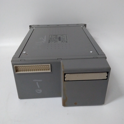
ICS TRIPLEX T3500备件模块,工控模块
与壳体两侧的导槽接合。4.从中心抓住锁定手柄并用力向下按压,将手柄从升高位置向装置底部旋转。5.当装置完全插入时,会听到门闩发出咔嗒声,将手柄锁定在最终位置。装置安装期间无需遵守特殊通风要求。该装置不需要清洁。警告2-6 469电机管理继电器GE Multilin 2.1机械2安装2 2.1.5端子位置图2–9:端子布局GE Multilin 469电机控制继电器2-7 2安装2.1机械2表2–1:469端子列表端子应涵盖仪表变压器输入、其他输入、输出、通信和接地的互连。端子布置见第2-6页图2–9:端子布置图和第2-7页表2–1:469端子列表。2.2.2控制电源469控制电源必须与安装的开关电源匹配。如果施加的电压不匹配,可能会损坏装置!抽出装置侧端子标签上的订单代码规定了标称控制电压,如下所示:•LO:20至60 V DC;20至48 V AC,或•HI:90至300 V DC;70至265 V AC确保施加的控制电压与抽出式外壳端子标签上的额定电压匹配。例如,HI电源将在90至300 V的直流电压或70至265 V的交流电压下工作。如果施加的电压超过此范围,内部保险丝可能会熔断。图2-11:控制电源连接469内置了广泛的滤波和瞬态保护,以确保在恶劣的工业环境中正常运行。瞬态能量必须通过滤波器接地端子传导回电源。为高压测试提供单独的安全接地端子。无论控制电源类型如何,必须连接所有接地以正常运行。警告2-10 469电机管理继电器GE Multilin 2.2电气2安装2 2.2.3电流输入a)相电流输入469有三个相电流输入通道,每个通道都有一个隔离变压器。电流输入上没有内部接地连接。如果装置被撤回,469外壳上的各相CT电路会被自动机构短路。应选择相位CT,使FLA不小于额定相位CT一次的50%。理想情况下,应选择CT初级相位,以使FLA为CT初级相位的100%,或稍小,绝不超过。这将确保电流测量的最大精度。最大相CT一次电流为5000 A。469可正确测量相电流额定值的20倍。由于转换范围较大,订购时必须指定1 A或5 A CT次级,以确保装置中安装了适当的插入式CT。所选CT必须能够驱动469相CT负载(额定值见第1-4页第1.2节:规范)。验证1 A或5 A的469标称相电流是否与所连接CT的次级额定值和连接相匹配。不匹配的CT可能导致设备损坏或保护不足。相位CT的极性对于负序不平衡计算、功率测量和剩余接地电流至关重要
engaged the guide slots on either side of the case. 4. Grasp the locking handle from the center and press down firmly, rotating the handle from the raised position toward the bottom of the unit. 5. When the unit is fully inserted, the latch will be heard to click, locking the handle in the final position. No special ventilation requirements need to be observed during the installation of the unit. The unit does not require cleaning. CAUTION 2-6 469 Motor Management Relay GE Multilin 2.1 MECHANICAL 2 INSTALLATION 2 2.1.5 TERMINAL LOCATIONS Figure 2–9: TERMINAL LAYOUT GE Multilin 469 Motor Management Relay 2-7 2 INSTALLATION 2.1 MECHANICAL 2 Table 2–1: 469 TERMINAL LIST TERMINA ll cover the interconnections of instrument transformer inputs, other inputs, outputs, communications, and grounding. See Figure 2–9: Terminal Layout on page 2–6 and Table 2–1: 469 TERMINAL LIST on page 2–7 for terminal arrangement. 2.2.2 CONTROL POWER The 469 control power must match the installed switching power supply. If the applied voltage does not match, damage to the unit may occur! The order code from the terminal label on the side of the drawout unit specifies the nominal control voltage as follows: • LO: 20 to 60 V DC; 20 to 48 V AC, or • HI: 90 to 300 V DC; 70 to 265 V AC Ensure applied control voltage and rated voltage on drawout case terminal label match. For example, the HI power supply will work with any DC voltage from 90 to 300 V, or AC voltage from 70 to 265 V. The internal fuse may blow if the applied voltage exceeds this range. Figure 2–11: CONTROL POWER CONNECTION Extensive filtering and transient protection are built into the 469 to ensure proper operation in harsh industrial environments. Transient energy must be conducted back to the source through the filter ground terminal. A separate safety ground terminal is provided for hi-pot testing. All grounds MUST be hooked up for normal operation regardless of control power supply type. CAUTION WARNING 2-10 469 Motor Management Relay GE Multilin 2.2 ELECTRICAL 2 INSTALLATION 2 2.2.3 CURRENT INPUTS a) PHASE CURRENT INPUTS The 469 has three channels for phase current inputs, each with an isolating transformer. There are no internal ground connections on the current inputs. If the unit is withdrawn, each phase CT circuit is shorted by automatic mechanisms on the 469 case. The phase CTs should be chosen so the FLA is no less than 50% of the rated phase CT primary. Ideally, the phase CT primary should be chosen such that the FLA is 100% of the phase CT primary or slightly less, never more. This will ensure maximum accuracy for the current measurements. The maximum phase CT primary current is 5000 A. The 469 correctly measures up to 20 times the phase current nominal rating. Since the conversion range is large, 1 A or 5 A CT secondaries must be specified at the time of order to ensure the appropriate interposing CT is installed in the unit. The chosen CTs must be capable of driving the 469 phase CT burden (see Section 1.2: Specifications on page 1–4 for ratings). Verify that the 469 nominal phase current of 1 A or 5 A matches the secondary rating and connections of the connected CTs. Unmatched CTs may result in equipment damage or inadequate protection. Polarity of the phase CTs is critical for Negative Sequence Unbalance calculation, power measurement, and residual ground current


