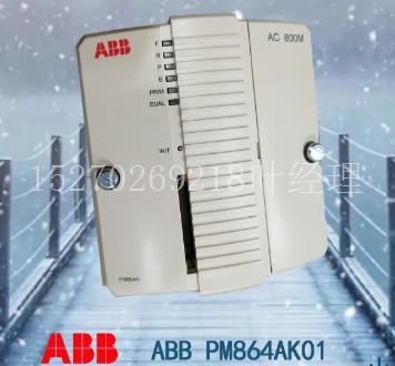
ICS TRIPLEX T8402 DCS工控模块备件
2 00 80设置点地址0080设置点数量2 00 02 2个设置点(总共4字节)字节计数1 04 2个寄存器=4字节命令功能2 00 05地址0080命令操作2 00 01地址0081 CRC 2 0B D6 CRC的数据由主从站响应计算:字节示例/描述从站11功能代码1 10的从站地址1 0B响应消息存储设置点数据起始地址2 00 80设置点地址0080设置点数量2 00 02 2个设置点(共4字节)CRC 2 40 8A由从属GE Power Management 469电机管理继电器6-15 6通信6.3错误响应6 6.3错误响应6.3.1描述当469检测到CRC错误以外的错误时,将向主控发送响应。FUNCTION CODE(功能代码)字节的MSbit将设置为1(即,从从机发送的功能代码将等于从主机发送的功能码加上128)。以下字节将是一个异常代码,指示发生的错误类型。469将忽略从具有CRC错误的主机接收的传输。从机对错误(CRC错误除外)的响应为:•从机地址:1字节•功能代码:1字节(MSbit设置为1)•异常代码:1个字节•CRC:2字节469实现以下异常响应代码。01-非法功能传输的功能代码不是469支持的功能之一。02-非法数据地址主机发送的数据字段中引用的地址不是469的允许地址。03-非法数据值主机传输的数据字段中引用的值不在所选数据地址的范围内。6-16 469电机管理继电器GE电源管理6.4存储器映射6通信6.4存储器映射6.4.1存储器映射信息469中存储的数据分为设定值和实际值。设置点可由主计算机读取和写入。实际值为只读。所有设定值和实际值存储为双字节值。也就是说,每个寄存器地址都是两字节值的地址。地址以十六进制列出。数据值(设定点范围、增量、出厂值)以十进制表示。许多Modbus通信驱动程序将40001d添加到寄存器地址的实际地址。例如:如果要读取地址0h,则40001d将是Modbus通信驱动程序所需的地址;如果要读取地址320h(800d),则40801d将是Modbus通信驱动程序所需的地址。6.4.2用户可定义的内存映射区域469具有一个强大的功能,称为用户可定义内存映射,允许计算机通过使用一个Modbus数据包读取多达124个非连续数据寄存器(设置点或实际值)。主计算机经常需要连续轮询每个连接的从属继电器中的各种值。如果这些值分散在整个内存映射中,那么读取它们将需要多次传输,并会给通信链路带来负担。用户可定义存储器映射可编程为将任何存储器映射地址连接到连续用户映射位置块中的一个,从而可以通过读取这些连续位置来访问它们。用户可定义区域有两个部分:1。包含125个实际值或设定点寄存器地址的寄存器索引区(存储器映射地址0180h至01FCh)。2.寄存器区域(存储器映射地址0100h至017Ch),其包含寄存器索引中的地址处的数据。在存储器映射的其余部分中分离的寄存器数据可以重新映射到用户可定义寄存器区域中的相邻寄存器地址。这是通过写入用户可定义的寄存器索引区域中的寄存器地址来实现的。这允许改进数据的吞吐量,并且可以消除对多个读取命令序列的需要。例如,如果平均相位的值
2 00 80 setpoint address 0080 NUMBER OF SETPOINTS 2 00 02 2 setpoints (4 bytes total) BYTE COUNT 1 04 2 registers = 4 bytes COMMAND FUNCTION 2 00 05 data for address 0080 COMMAND OPERATION 2 00 01 data for address 0081 CRC 2 0B D6 CRC calculated by the master SLAVE RESPONSE: BYTES EXAMPLE / DESCRIPTION SLAVE ADDRESS 1 0B response message from slave 11 FUNCTION CODE 1 10 store setpoints DATA STARTING ADDRESS 2 00 80 setpoint address 0080 NUMBER OF SETPOINTS 2 00 02 2 setpoints (4 bytes total) CRC 2 40 8A CRC calculated by the slave GE Power Management 469 Motor Management Relay 6-15 6 COMMUNICATIONS 6.3 ERROR RESPONSES 6 6.3 ERROR RESPONSES 6.3.1 DESCRIPTION When an 469 detects an error other than a CRC error, a response will be sent to the master. The MSbit of the FUNCTION CODE byte will be set to 1 (i.e. the function code sent from the slave will be equal to the function code sent from the master plus 128). The following byte will be an exception code indicating the type of error that occurred. Transmissions received from the master with CRC errors will be ignored by the 469. The slave response to an error (other than CRC error) will be: • SLAVE ADDRESS: 1 byte • FUNCTION CODE: 1 byte (with MSbit set to 1) • EXCEPTION CODE: 1 byte • CRC: 2 bytes The 469 implements the following exception response codes. 01 - ILLEGAL FUNCTION The function code transmitted is not one of the functions supported by the 469. 02 - ILLEGAL DATA ADDRESS The address referenced in the data field transmitted by the master is not an allowable address for the 469. 03 - ILLEGAL DATA VALUE The value referenced in the data field transmitted by the master is not within range for the selected data address. 6-16 469 Motor Management Relay GE Power Management 6.4 MEMORY MAP 6 COMMUNICATIONS 6 6.4 MEMORY MAP 6.4.1 MEMORY MAP INFORMATION The data stored in the 469 is grouped as Setpoints and Actual Values. Setpoints can be read and written by a master computer. Actual Values are read only. All Setpoints and Actual Values are stored as two-byte values. That is, each register address is the address of a two-byte value. Addresses are listed in hexadecimal. Data values (setpoint ranges, increments, factory values) are in decimal. Many Modbus communications drivers add 40001d to the actual address of the register addresses. For example: if address 0h was to be read, 40001d would be the address required by the Modbus communications driver; if address 320h (800d) was to be read, 40801d would be the address required by the Modbus communications driver. 6.4.2 USER DEFINABLE MEMORY MAP AREA The 469 has a powerful feature, called the User Definable Memory Map, which allows a computer to read up to 124 non-consecutive data registers (setpoints or actual values) by using one Modbus packet. It is often necessary for a master computer to continuously poll various values in each of the connected slave relays. If these values are scattered throughout the memory map, reading them would require numerous transmissions and would burden the communication link. The User Definable Memory Map can be programmed to join any memory map address to one in the block of consecutive User Map locations, so that they can be accessed by reading these consecutive locations. The User Definable area has two sections: 1. A register index area (memory map addresses 0180h to 01FCh) that contains 125 actual values or setpoints register addresses. 2. A register area (memory map addresses 0100h to 017Ch) that contains the data at the addresses in the register index. Register data that is separated in the rest of the memory map may be remapped to adjacent register addresses in the User Definable Registers area. This is accomplished by writing to register addresses in the User Definable Register Index area. This allows for improved through-put of data and can eliminate the need for multiple read command sequences. For example, if the values of Average Phase


