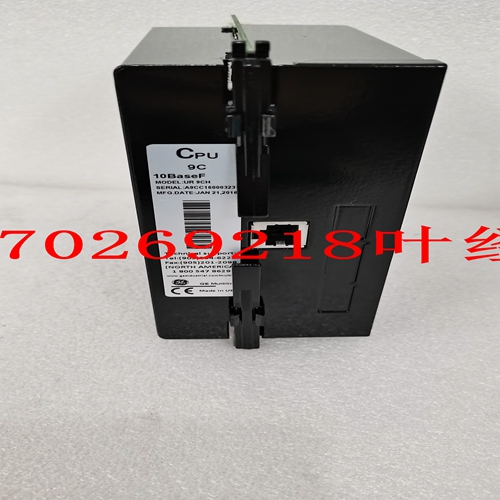
IS200BICIH1ADB IS200GGXDG1ABB备件库存,机械备件
当这些触点断开时,如起动器状态数字输入监控断路器辅助触点所检测到的,跳闸线圈监控电路将自动禁用。该逻辑允许仅在断路器闭合时监测跳闸电路。•R2辅助、R3辅助:辅助继电器可编程用于跳闸回声、报警回声、跳闸备用、报警区分、控制电路和许多其他功能。它们应根据配置保证进行接线。•R4报警:报警继电器应连接到适当的报警器或监控装置。•R5块启动:块启动继电器应与断路器或接触器配置中的启动按钮串联,以防止电机启动。当断路器上的跳闸未复位时,闭锁启动继电器会阻止启动尝试,从而导致立即跳闸。此外,任何锁定功能都指向块启动继电器。•R6维修:如果469诊断中的任何一个检测到内部故障或控制电源丢失,维修继电器将工作。该输出可通过报警器、PLC或DCS进行监控。如果认为电机比过程更重要,维修继电器NC触点也可以与断路器应用中的跳闸继电器并联连接,或者NO触点可以与接触器应用中的脱扣继电器串联连接。这将提供电机的故障安全操作;也就是说,如果469没有保护电机,电机将从线路上跳闸。但是,如果过程是关键的,则此类故障的通知将允许操作员或操作计算机继续或顺序停机。详情请参见第2-19页图2-22:接触器的备用接线。GE Power Management 469电机管理继电器2-19 2安装2.2电气2图2-22:接触器的备用接线2.2.13拉出指示器拉出指示器只是端子E12至F12之间的跳线。当469从外壳中取出时,端子E12和F12断开。这可能有助于区分R6 SERVICE继电器指示的控制功率损失和装置的退出。2-20 469电机管理继电器GE Power Management 2.2电气2安装2 2.2.14 RS485通信端口提供两个独立的双线RS485端口。多达32 469可以在通信信道上菊花链连接在一起,而不超过驱动器的能力。对于较大的系统,必须添加额外的串行通道。商用中继器还可用于增加
When these contacts are open, as detected by the Starter Status Digital Input monitoring breaker auxiliary contacts, trip coil supervision circuit is automatically disabled. This logic allows the trip circuit to be monitored only when the breaker is closed. • R2 AUXILIARY, R3 AUXILIARY: The auxiliary relays may be programmed for trip echo, alarm echo, trip backup, alarm differentiation, control circuitry, and numerous other functions. They should be wired as configuration warrants. • R4 ALARM: The alarm relay should connect to the appropriate annunciator or monitoring device. • R5 BLOCK START: The block start relay should be wired in series with the start push-button in either a breaker or contactor configuration to prevent motor starting. When a trip has not been reset on a breaker, the block start relay prevents a start attempt that would result in an immediate trip. Also, any lockout functions are directed to the block start relay. • R6 SERVICE: The service relay operates if any of the 469 diagnostics detect an internal failure or on loss of control power. This output may be monitored with an annunciator, PLC or DCS. If it is deemed that a motor is more important than a process, the service relay NC contact may also be wired in parallel with the trip relay on a breaker application or the NO contact may be wired in series with the trip relay on a contactor application. This will provide failsafe operation of the motor; that is, the motor will be tripped off line in the event that the 469 is not protecting it. If however, the process is critical, annunciation of such a failure will allow the operator or the operation computer to either continue, or do a sequenced shutdown. See Figure 2–22: ALTERNATE WIRING FOR CONTACTORS on page 2–19 for details. GE Power Management 469 Motor Management Relay 2-19 2 INSTALLATION 2.2 ELECTRICAL 2 Figure 2–22: ALTERNATE WIRING FOR CONTACTORS 2.2.13 DRAWOUT INDICATOR The Drawout Indicator is simply a jumper from terminals E12 to F12. When the 469 is withdrawn from the case, terminals E12 and F12 are open. This may be useful for differentiating between loss of control power as indicated by the R6 SERVICE relay and withdrawal of the unit. 2-20 469 Motor Management Relay GE Power Management 2.2 ELECTRICAL 2 INSTALLATION 2 2.2.14 RS485 COMMUNICATIONS PORTS Two independent two-wire RS485 ports are provided. Up to 32 469s can be daisy-chained together on a communication channel without exceeding the driver capability. For larger systems, additional serial channels must be added. Commercially available repeaters can also be used to add more than


