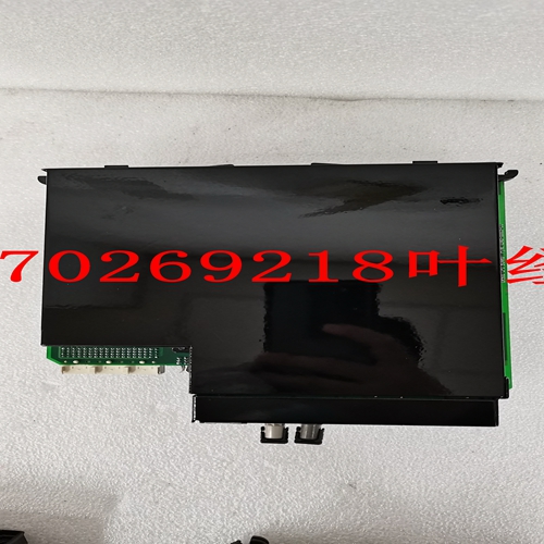
IS200BICLH1A DCS模块卡件,工控模块卡件
继电器2-17 2安装2.2电气2 c)双线RTD引线补偿下图显示了如何将引线补偿添加到双线RTD的示例。图2–20:2线RTD引线补偿增加补偿引线L2,以补偿热(L1)和回流(L3),假设它们都具有相同的长度和规格。为了补偿导线RL1和RL2,可以在补偿导线上增加一个等于RL1或RL2电阻的电阻,尽管在许多情况下这是不必要的。d) RTD接地RTD的一根引线在469或电机处接地。不应在两个地方进行接地,因为这可能会导致循环电流流动。只有RTD回路引线可以接地。在469处接地时,只有一根回流导线需要接地,因为它们内部硬接线在一起。通过这种方式接地,RTD读数不会出现误差。如果RTD回路引线连接在一起并在电机处接地,则只能将一条RTD回路引线引回469。有关接线示例,请参见下图。在469上运行多条RTD回路导线会导致严重错误,因为已经为回路电流创建了两条或多条并联路径。使用此接线方案会导致读数错误,与前面描述的REDUCED RTD LEAD NUMBER(减少RTD引线编号)应用程序中的读数相同。图2-21:RTD交流接地2-18 469电机管理继电器GE Power Management 2.2电气2安装2 2.2.12输出继电器共有六个C型输出继电器(详见第1-5页第1.2节:规范)。六个继电器中的五个始终是非故障安全的;R6服务始终是故障安全的。作为故障保护,R6继电器通常通电,并在需要操作时断电。当469控制电源丢失并将处于其操作状态时,它也会断电。所有其他非故障保护继电器通常在需要操作时断电和通电。当469控制电源丢失时,这些继电器断电并处于非操作状态。抽出式外壳中的短路杆确保在抽出469时不会发生跳闸或报警。然而,R6服务输出将指示469已被取出。每个输出继电器在前面板上有一个LED指示灯,当相关继电器处于工作状态时,该指示灯点亮。•R1跳闸:跳闸继电器应接线,以便在条件允许时使电机离线。对于断路器应用,NO R1跳闸触点应与断路器跳闸线圈串联。对于接触器应用,NC R1跳闸触点应与接触器线圈串联连接。断路器跳闸线圈的监控要求监控电路与R1跳闸继电器输出触点并联,如第2-8页图2-10:典型接线图所示。通过这种连接,监控输入电路在触点两端设置阻抗,通过断路器跳闸线圈抽取2 mA电流(对于30至250 V DC的外部电源电压)。监控电路将此涓流电流的损失作为故障条件进行响应。配备标准控制电路的断路器具有断路器辅助触点,仅当断路器闭合时,才允许跳闸线圈通电。
Relay 2-17 2 INSTALLATION 2.2 ELECTRICAL 2 c) TWO WIRE RTD LEAD COMPENSATION An example of how to add lead compensation to a two wire RTD may is shown in the figure below. Figure 2–20: 2 WIRE RTD LEAD COMPENSATION The compensation lead L2 is added to compensate for Hot (L1) and Return (L3), assuming they are all of equal length and gauge. To compensate for leads RL1 and RL2, a resistor equal to the resistance of RL1 or RL2 could be added to the compensation lead, though in many cases this is unnecessary. d) GROUNDING OF RTDs Grounding of one lead of the RTDs is done at either the 469 or at the motor. Grounding should not be done in both places as it could cause a circulating current to flow. Only RTD Return leads may be grounded. When grounding at the 469, only one Return lead need be grounded as they are hard-wired together internally. No error is introduced into the RTD reading by grounding in this manner. If the RTD Return leads are tied together and grounded at the motor, only one RTD Return lead can be run back to the 469. See the figure below for a wiring example. Running more than one RTD Return lead to the 469 causes significant errors as two or more parallel paths for the return current have been created. Use of this wiring scheme causes errors in readings equivalent to that in the REDUCED RTD LEAD NUMBER application described earlier. Figure 2–21: RTD ALTERNATE GROUNDING 2-18 469 Motor Management Relay GE Power Management 2.2 ELECTRICAL 2 INSTALLATION 2 2.2.12 OUTPUT RELAYS There are six Form C output relays (see Section 1.2: SPECIFICATIONS on page 1–5 for details). Five of the six relays are always non-failsafe; R6 Service is always failsafe. As failsafe, the R6 relay is normally energized and de-energizes when called upon to operate. It also de-energizes when 469 control power is lost and will be in its operated state. All other relays, being non-failsafe, will normally be de-energized and energize when called upon to operate. When the 469 control power is lost, these relays are de-energized and in their nonoperated state. Shorting bars in the drawout case ensure that no trip or alarm occurs when the 469 is drawn out. However, the R6 Service output will indicate that the 469 has been drawn out. Each output relay has an LED indicator on the front panel that turns on when the associated relay is in the operated state. • R1 TRIP: The trip relay should be wired to take the motor off line when conditions warrant. For a breaker application, the NO R1 Trip contact should be wired in series with the Breaker trip coil. For contactor applications, the NC R1 Trip contact should be wired in series with the contactor coil. Supervision of a breaker trip coil requires that the supervision circuit be in parallel with the R1 TRIP relay output contacts, as shown in Figure 2–10: TYPICAL WIRING DIAGRAM on page 2–8. With this connection made, the supervision input circuits place an impedance across the contacts that draws a 2 mA current (for an external supply voltage from 30 to 250 V DC) through the breaker trip coil. The supervision circuits respond to a loss of this trickle current as a failure condition. Circuit breakers equipped with standard control circuits have a breaker auxiliary contact permitting the trip coil to be energized only when the breaker is closed.


