


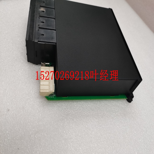
IS200F0SAG1AAA自动化模块备件
ZRSG实施应扩展到包括所有设备机架和互连电缆路径:金属导管、电缆槽、电线槽等。详细安装指南可参见:EPRI TR-102400,第2卷,发电厂数字设备电磁兼容性手册,EMI控制实施指南IEC 61000,第5部分,第2节,电磁兼容性(EMC)、安装和缓解指南、接地和布线IEEE Std 1100-1999、IEEE电子设备供电和接地推荐规程170第3章Tricon v9–v10系统的安装和维护规划与安装指南Tricon Field,Power,所有Tricon配电和安全接地(保护接地)必须按照适用的国家电气规范以及本手册中包含的信息进行,典型示例包括:IEC 60364《建筑物电气安装国家防火协会》,2002版《国家电气规范手册》,Tricon将安装在控制室内的设备机架或机柜中。该机柜内部和从该机柜引出的所有接线应分为不同类型,并相应捆绑,例如:•测量信号-通常来自传感器的非常敏感的低压信号:RTD、TC、速度或流量传感器等。这些信号通常需要屏蔽双绞线。•测量和低功率控制信号-通常为敏感的低压信号,用于/形成智能传感器或控制设备:4-20毫安回路、24 VDC离散信号等。这些信号通常需要双绞线。•高功率控制信号和调节配电-通常不敏感,较高电压信号:48-120伏离散信号、24-120 VDC I/O配电等。这些信号应始终使用双绞线电缆。•输入输入功率和杂项。电路-通常是噪声较大的高功率电路-115 VAC离散信号、交流配电、机柜风扇或灯等。这些信号应始终使用双绞线电缆,接地电极导体(绿线)应尽可能与电源线一起绞合。•接地连接。所有电缆布线和安装都应尽量减少EMI,详细指南可参见:EPRI TR-102400,第2卷,发电厂数字设备电磁兼容性手册,EMI控制实施指南IEC 61000-5-2,电磁兼容性(EMC),安装和缓解指南,接地和布线IEEE标准1100-1999,IEEE电子设备通电和接地推荐规程典型指南包括:•使用黑色金属柜、电缆槽和导管。•当RS-485 I/O总线用于连接到远程扩展机箱时,I/O总线电缆必须在专用金属导管中布线或与其他噪声源等效隔离。•用多个导电金属带(而不是简单的电线)将机柜的所有表面及其内容物电连接在一起。应特别注意门和可拆卸面板。反过来,机柜必须连接到控制室或工厂安全接地系统或ZRSG。安装指南171 Tricon v9–v10系统规划和安装指南•常规使用双绞线布线;对所有敏感信号使用屏蔽双绞线。允许容纳连接的最小数量的非绞合线。•不同类型的信号不应捆绑在一起。•不同类型的线束之间的间距应至少为最大导线直径的10倍。•不同类型的信号束只能以直角交叉。•所有电线和/或线束应沿ZRSG布线;例如,沿着机柜壁、电缆槽或导管内、沿着建筑钢或地板接地网。•在使用内联滤波器或电源调节的情况下,输入和输出导线不应在同一线束中布线。
The ZRSG implementation should be extended to include all equipment racks and interconnecting cable paths: metal conduits, cable trays, wireways, etc. Detailed installation guidelines can be found in: EPRI TR- 102400, Volume 2, Handbook for Electromagnetic Compatibility of Digital Equipment in Power Plants, Implementation Guide for EMI Control IEC 61000, Part 5, Section 2, Electromagnetic compatibility (EMC), Installation and mitigation guidelines, Earthing and cabling IEEE Std 1100-1999, IEEE Recommended Practice for Powering and Grounding Electronic Equipment 170 Chapter 3 Installation and Maintenance Planning and Installation Guide for Tricon v9–v10 Systems Tricon Field, Power, and Ground Wiring All Tricon power distribution and safety grounding (protective earthing) must be done per the applicable national electric codes, plus the information contained in this manual, typical examples include: IEC 60364, Electrical Installations of Buildings National Fire Protection Association, 2002 Edition of the National Electrical Code Handbook Typically, the Tricon will be installed in an equipment rack or cabinet located in a control room. All wiring internal to that cabinet and leading to from that cabinet should be segregated into different types and bundled accordingly, for example: • Measurement signals - typically very sensitive, low voltage signals from sensors: RTDs, TCs, speed or flow sensors, etc. These signals will typically require shielded twisted pair cabling. • Measurement and low power control signals - typically sensitive, low voltage signals to/form intelligent sensors or control devices: 4-20 ma loops, 24 VDC discrete signals, etc. These signals will typically require twisted pair cabling. • High power control signals and conditioned power distribution - typically not sensitive, higher voltage signals: 48-120 volt discrete signals, 24-120 VDC I/O power distribution, etc. These signals should always use twisted pair cabling. • Input coming power and misc. circuits - typically noisy, higher power circuits - 115 VAC discrete signals, AC power distribution, cabinet fans or lights, etc. These signals should always use twisted pair cabling, and the Grounding Electrode Conductor (the green wire) should be twisted along with the power leads wherever possible. • Earth bonding connections. All cable routing and installation should be done to minimize EMI, detailed guidelines can be found in: EPRI TR- 102400, Volume 2, Handbook for Electromagnetic Compatibility of Digital Equipment in Power Plants, Implementation Guide for EMI Control IEC 61000-5-2, Electromagnetic compatibility (EMC), Installation and mitigation guidelines, Earthing and cabling IEEE Std 1100-1999, IEEE Recommended Practice for Powering and Grounding Electronic Equipment Typical guidelines include the following: • Use ferrous metal cabinets, cable trays, and conduits. • When the RS-485 I/O Bus is used to connect to a remote Expansion Chassis, the I/O Bus cables must be routed in dedicated metallic conduit or equivalently isolated from other noise sources. • Electrically bond all surfaces of the cabinet and it's contents together with multiple conductive metal strapping, not simple wire. Particular attention should be paid to doors, and removable panels. In turn the cabinet must be bonded to the control room or plant safety ground system or ZRSG. Installation Guidelines 171 Planning and Installation Guide for Tricon v9–v10 Systems • Routinely use twisted pair cabling; use shielded twisted pair cabling for all sensitive signals. Allow the minimum amount of un-twisted wire that accommodates connection. • Signals of different types should never be bundled together. • Bundles of different types should be separated by a minimum of 10 times the largest lead diameter. • Bundles of different types of signals should only cross at right angles to each other. • All wires and/or bundles should be routed along the ZRSG; for example, along the cabinet walls, within a cable tray or conduit, along building steel or the floor ground grid. • Where an inline filter or power conditioning is used, the input and output leads should never be routed in the same bundle.
")
")
")
")
")

