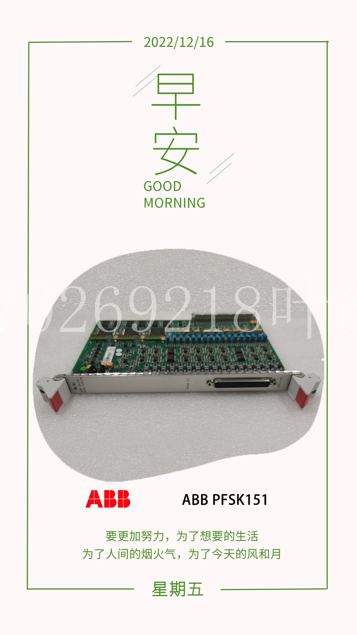
IS200ICBDH1ACB机器人卡件
Triconex保证OVD强制故障具有以下持续时间:•对于交流模块,不超过1/2交流周期。•对于直流模块,小于2毫秒(通常为500微秒),这是继电器、电磁阀和接触器等机电设备可以容忍的时间。如果受控过程需要,OVD可以被禁用,但必须定期循环到打开和关闭状态,以确保100%的故障覆盖率。对于不能容忍任何长度的信号转换的设备,可以禁用交流和直流电压数字输出模块上的OVD。有关更多信息,请参阅第214页禁用DO模块上的输出表决器诊断。交流电压数字输出模块在交流电压数字输入模块上,OVD过程识别的故障开关会导致输出信号转换到相反的状态,最多持续1/2个交流周期。这种转换可能对所有现场设备都不透明。一旦检测到故障,模块将停止OVD的进一步迭代。如果受控过程需要,OVD可以被禁用,但必须定期循环到打开和关闭状态,以确保100%的故障覆盖率。直流电压数字输出模块直流电压数字输入模块专门设计用于控制长时间将点保持在一个状态的设备。直流电压数字输出模块的OVD策略确保即使点的命令状态从未改变,也能完全覆盖故障。在这种类型的模块上,输出信号转换通常发生在OVD执行期间,但保证小于2.0毫秒(通常为500微秒),并且对大多数现场设备是透明的。如果受控过程需要,OVD可以被禁用,但必须定期循环到打开和关闭状态,以确保100%的故障覆盖率。数字输出模块89 Tricon v9–v10系统的规划和安装指南继电器输出模块继电器输出(RO)模块是非三重模块,用于与高端固态输出开关(如信号器面板)不兼容的非关键点。继电器输出模块在三个通道中的每个通道上接收来自主处理器的输出信号。然后对三组信号进行表决,表决后的数据用于驱动32个单独的继电器。每个输出都有一个环回电路,该电路独立于负载的存在来验证每个继电器开关的操作。持续诊断测试反渗透模块的运行状态,该模块不适用于临界点或现场负载切换。监控数字输出模块监控数字输出(SDO)模块提供电压和电流环回,允许对通电跳闸和断电跳闸条件进行完全故障覆盖。SDO模块监控现场电路,以便可以检测到这些现场故障:断电或保险丝熔断、负载开路或缺失、导致负载错误通电的现场短路以及断电状态下的短路负载。模块会通知任何现场负载损失。115 VAC数字输出模块本图为3601E和3601T型TMR数字输出模块的简化示意图。图36 3601E和3601T简化示意图点寄存器mProc总线Xcvr点寄存器mProc总线Xcvr点寄存器mProc总线Xccr总线Xcvr点寄存器总线Xcvr-点寄存器总线Xcvr点寄存器输出开关驱动电路A A和B输出开关驱动线路输出开关驱动电路B输出开关驱动器电路C A B C A和B B C+V A B C TRIPLICATED I/O总线场电路–典型点(16)电压环回检测器LD RTN智能I/O控制器***所有输出开关均为光隔离。μProcμProc 90第2章Tricon v9–v10系统的系统组件规划和安装指南此图显示了3601E和3601T型号的前面板。图37 3601E和3601T前面板绿色条纹数字输出模块91 Tricon v9–v10系统规划和安装指南3601E和360 1T规格本表列出了3601E和3600 1T型号的规格,它们是16点光隔离TMR数字输出模块,标称电压为115 VAC。3601T型具有更高的点隔离最小值。表31 3601E和3601T数字输出规格功能规格颜色代码绿色输出信号数量16,非公用输入频率范围47-63 Hz电压范围80–155 VAC逻辑功率<10瓦额定电流,最大2安培/点,12安培浪涌/周期负载泄漏电流@60 Hz最大2 mA
Triconex guarantees that an OVD-forced glitch has the following durations: • For AC modules, no longer than 1/2 AC cycle. • For DC modules, less than 2 milliseconds (typically 500 microseconds), which is a period that is tolerated well by electro-mechanical devices such as relays, solenoids and contactors. If required by the controlled process, OVD can be disabled, however it must be periodically cycled to both the On and Off states to ensure 100 percent fault coverage. For devices that cannot tolerate a signal transition of any length, OVD on both AC and DC voltage Digital Output Modules can be disabled. For more information, see Disabling Output Voter Diagnostics on DO Modules on page 214. AC Voltage Digital Output Modules On AC voltage Digital Output Modules, a fault switch identified by the OVD process causes the output signal to transition to the opposite state for a maximum of 1/2 an AC cycle. This transition may not be transparent to all field devices. Once a fault is detected, the module discontinues further iterations of OVD. If required by the controlled process, OVD can be disabled, however it must be periodically cycled to both the On and Off states to ensure 100 percent fault coverage. DC Voltage Digital Output Modules DC voltage Digital Output Modules are specifically designed to control devices which hold points in one state for long periods of time. The OVD strategy for a DC voltage Digital Output Module ensures full fault coverage even if the commanded state of the points never changes. On this type of module, the output signal transition normally occurs during OVD execution, but is guaranteed to be less than 2.0 milliseconds (500 microseconds is typical) and is transparent to most field devices. If required by the controlled process, OVD can be disabled, however it must be periodically cycled to both the On and Off states to ensure 100 percent fault coverage. Digital Output Modules 89 Planning and Installation Guide for Tricon v9–v10 Systems Relay Output Modules Relay Output (RO) Modules are non-triplicated modules for use on non-critical points which are not compatible with high-side solid-state output switches, such as annunciator panels. Relay Output Modules receive output signals from the Main Processors on each of three channels. The three sets of signals are then voted, and the voted data is used to drive the 32 individual relays. Each output has a loopback circuit which verifies the operation of each relay switch independently of the presence of a load. Ongoing diagnostics test the operational status of the RO Module, which is not intended for use on critical points or switching of field loads. Supervised Digital Output Modules Supervised Digital Output (SDO) Modules provide both voltage and current loopback, allowing complete fault coverage for both energized-to-trip and de-energized-to-trip conditions. SDO modules supervise the field circuit so these field faults can be detected: loss of power or blown fuse, open or missing load, field short resulting in the load being energized in error, and shorted load in the de-energized state. Any loss of field load is annunciated by the module. 115 VAC Digital Output Modules This figure is a simplified schematic for models 3601E and 3601T, which are TMR Digital Output Modules. Figure 36 3601E and 3601T Simplified Schematic Point Register mProc Bus Xcvr Point Register mProc Bus Xcvr Point Register mProc Bus Xcvr Bus Xcvr Point Register Bus Xcvr Point Register Bus Xcvr Point Register Output Switch Drive Circuitry A A and B Output Switch Drive Circuitry Output Switch Drive Circuitry B Output Switch Drive Circuitry C A B C A and B A B C +V A B C TRIPLICATED I/O BUS FIELD CIRCUITRY – TYPICAL POINT (16) Voltage Loopback Detector LD RTN INTELLIGENT I/O CONTROLLER(S) * * * * * All output switches are opto-isolated. μProc μProc μProc 90 Chapter 2 System Components Planning and Installation Guide for Tricon v9–v10 Systems This figure shows the front panels of models 3601E and 3601T. Figure 37 3601E and 3601T Front Panels Green Stripe Digital Output Modules 91 Planning and Installation Guide for Tricon v9–v10 Systems 3601E and 3601T Specifications This table lists the specifications for models 3601E and 3601T, which are 16-point, opto-isolated TMR Digital Output Modules with an nominal voltage of 115 VAC. Model 3601T has a higher point-isolation minimum. Table 31 3601E and 3601T Digital Output Specifications Feature Specification Color code Green Number of output signals 16, non-commoned Input frequency range 47-63 Hz Voltage range 80–155 VAC Logic power < 10 watts Current ratings, maximum 2 amps/point, 12 amps surge/cycle Leakage current to load @ 60 Hz 2 mA maximum


