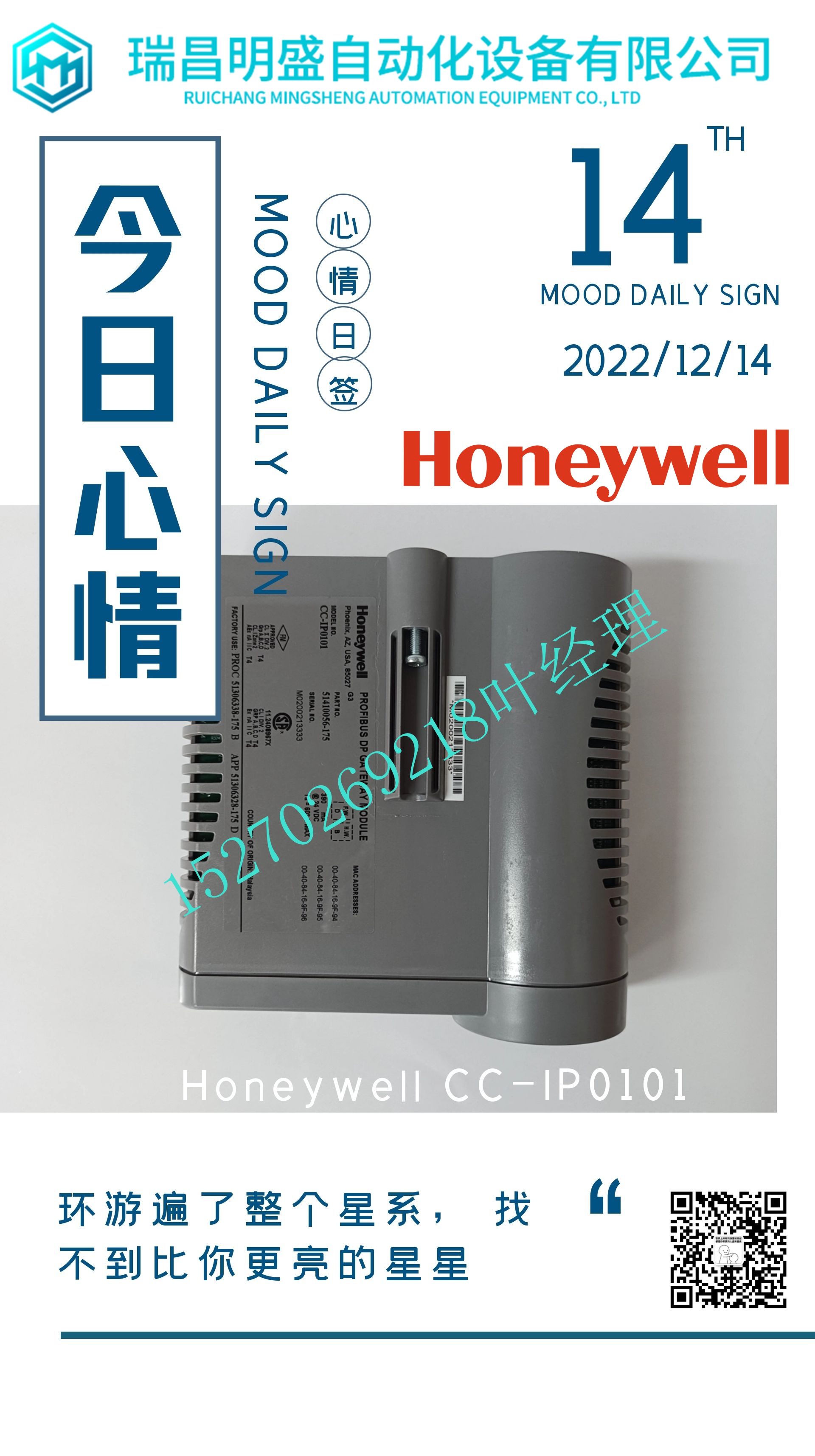
IS200ICIAH1AAB处理器模块,工控模块
表27 3505E数字输入规格特性规格颜色代码深红色输入点32的数量,共8组建议输入范围20–42.5 VDC最大电压42.5 VDC开关电平:典型的断开至接通10 VDC,最坏情况下为12 VDC开关电平,典型的接通至断开5 VDC,4 VDC最坏情况典型滞后2 VDC标称接通3 mA至5 mA输入阻抗>1.25 kΩ标称输入延迟:断开至接通<8 ms输入延迟:接通至断开<15 ms点隔离,最小光隔离1000 VAC,最小1500 VDC状态指示器:每点接通或断开状态1状态指示器:模块状态通过,故障,活动逻辑功率<10瓦标称现场功率负载0.5瓦/开点1 1.5瓦@最大现场电压底盘泄漏电流@60 Hz 0.25 mA/开点输入诊断故障范围2:最大输入切换率最小输入切换率,开状态最小输入切换速率,关闭状态每100 ms不需要每3个月(由用户手动切换)诊断故障持续时间3输出电压输出阻抗20 ms典型值<1/2 VIN<1.87 kΩ80第2章Tricon v9–v10系统24至48 VDC数字输入模块的系统组件规划和安装指南此图为3504E型的简化示意图,其是高密度TMR数字输入模块。图32 3504E简化示意图1。当与典型的并联二极管本质安全栅一起使用时,每个接通点的标称场功率约为350毫瓦@24 VDC。2.最大输入切换率可实现I/O诊断的正确操作和所有正常可检测故障的检测。最小切换率提供了模块计算平均故障间隔时间(MTBF)10%内正常不可检测故障的故障覆盖率。3.VIN是施加到通电点的电压。在诊断故障持续期间,相邻断电点上的输出电压很明显。请注意,故障输出可能会错误地激励另一台设备的并联输入。总线Xcvr总线XcvrBus Xcvr A B C ADC单个点场特性隔离/滤波每个支路的独立ADC智能I/O控制器(S)三重I/O总线信号调节高密度数字输入电路–典型点(64个中的1个)Amp Mux Amp MuxAmp Mux-Hi-Ref Hi-Ref Lo-Ref Lo-Ref ADCµProcµProc数字输入模块81规划和Tricon v9–v10系统安装指南此图显示了3504E型的前面板。图33 3504E前面板HDDI 3504E PASS FAULT ACTIVE 1 2 3 4 5 6 7 8 9 10 11 12 13 14 15 16 17 18 19 20 21 22 23 24 25 26 27 29 30 31 33 34 35 36 37 38 39 40 42 43 44 45 46 47 49 50 51 52 54 55 56 58 59 60 61 62 63 64深红色条纹24VDC/48VDC 82第2章Tricon v9–v10系统3504E规格的系统组件规划和安装指南本表列出了3504E型为高密度TMR数字输入模块,标称输入电压为24或48 VDC。表28 3504E数字输入规格特性规格颜色代码深红色输入点64个,共用,直流耦合输入电压范围:24 VDC1 1。在TriStation软件中指定。20–36 VDC输入电压范围:48 VDC 40–72 VDC输入超范围保护115 VAC连续,
Table 27 3505E Digital Input Specifications Feature Specification Color code Dark red Number of input points 32, commoned in groups of 8 Recommended input range 20–42.5 VDC Maximum voltage 42.5 VDC Switching level: Off to On 10 VDC typical, 12 VDC worst-case Switching level: On to Off 5 VDC typical, 4 VDC worst-case Typical hysteresis 2 VDC Nominal turn-on 3 mA to 5 mA Input impedance > 1.25 kΩ nominal Input delay: Off to On < 8 ms Input delay: On to Off < 15 ms Point isolation, opto-isolated 1000 VAC minimum, 1500 VDC minimum Status indicator: On or Off State 1 per point Status indicator: Module status Pass, Fault, Active Logic power < 10 watts Nominal field power load 0.5 watts per On point1 1.5 watts @ maximum field voltage Leakage current to chassis @ 60 Hz 0.25 mA maximum per On point Input diagnostic fault coverage2: Maximum input toggle rate Minimum input toggle rate, On state Minimum input toggle rate, Off state Every 100 ms Not required Every 3 months (manually toggled by the user) Diagnostic glitch duration3 Output voltage Output impedance 20 ms typical < 1/2 VIN < 1.87 kΩ 80 Chapter 2 System Components Planning and Installation Guide for Tricon v9–v10 Systems 24 to 48 VDC Digital Input Modules This figure is a simplified schematic for model 3504E, which is a high-density TMR Digital Input Module. Figure 32 3504E Simplified Schematic 1. When used with a typical shunt-diode intrinsic safety barrier, the nominal field power per On point is approximately 350 milliwatts @ 24 VDC. 2. The maximum input toggle rate enables proper operation of I/O diagnostics and detection of all normally detectable faults. The minimum toggle rate provides fault coverage of normally undetectable faults within 10% of the calculated mean-time-between-faults (MTBF) for the module. 3. VIN is the voltage applied to an energized point. Output voltage is noticeable on an adjacent deenergized point for the duration of the diagnostic glitch. Be advised that the glitch output may falsely energize the paralleled input of another piece of equipment. Bus Xcvr Bus Xcvr Bus Xcvr A B C ADC Individual Point Field Te mr inations Isolation/ Filtering INDIVIDUAL ADC FOR EACH LEG INTELLIGENT I/O CONTROLLER(S) TRIPLICATED I/O BUS SIGNAL CONDITIONING HIGH-DENSITY DIGITAL INPUT CIRCUIT – TYPICAL POINT (1 of 64) Amp Mux Amp Mux Amp Mux Hi Ref Lo Ref Hi Ref Lo Ref Hi Ref Lo Ref ADC ADC µProc µProc µProc Digital Input Modules 81 Planning and Installation Guide for Tricon v9–v10 Systems This figure shows the front panel of model 3504E. Figure 33 3504E Front Panel HDDI 3504E PASS FAULT ACTIVE 1 2 3 4 5 6 7 8 9 10 11 12 13 14 15 16 17 18 19 20 21 22 23 24 25 26 27 28 29 30 31 32 33 34 35 36 37 38 39 40 42 43 44 45 46 47 48 49 50 51 52 53 54 55 56 57 58 59 60 61 62 63 64 Dark Red Stripe 24VDC/48VDC 82 Chapter 2 System Components Planning and Installation Guide for Tricon v9–v10 Systems 3504E Specifications This table lists the specifications for model 3504E, which is a high-density TMR Digital Input Module with an nominal input voltage of 24 or 48 VDC. Table 28 3504E Digital Input Specifications Feature Specification Color code Dark red Number of input points 64, commoned, DC-coupled Input voltage range: 24 VDC1 1. Specified in the TriStation software. 20–36 VDC Input voltage range: 48 VDC1 40–72 VDC Input over-range protection 115 VAC continuous,


