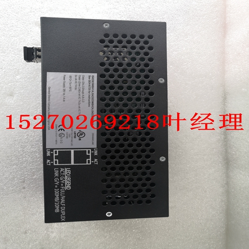
IS200ISBBG1A机器人卡件
如果开路输入(<0 VDC)超出量程下限,主处理器将接收整数值–32767。如果开路输入(>5 VDC或10 VDC)超出量程上限,主处理器将接收整数值+32767。3720和3721可在TriStation 1131中配置为标准(12位)分辨率或高(14位)分辨率。在高分辨率下,3721可在TriStation 1131中配置为单极(0至5 VDC)或双极(-5至+5 VDC)输入。每个模拟输入模块为每个通道提供完整的持续诊断。任何通道上的任何诊断失败都会激活模块的故障指示灯,进而激活底盘报警信号。故障指示灯指示通道故障,而不是模块故障。模块保证在出现单个故障时正常运行,并且在出现一些多个故障时可以继续正常运行。模拟输入模块包括热备用功能,允许在线更换故障模块。与所有I/O模块一样,模拟输入模块需要一个单独的现场终端组件,该组件带有到Tricon控制器背板的电缆接口。每个模块都采用机械键控,以防止在配置的机箱中安装不当。表11模拟输入模块型号电压范围类型模块说明3700 3700A 0–5 VDC TMR模拟输入3701 0–10 VDC TMR模拟输出3703E 0–5或0–10 VDC TMR隔离模拟输入3704E 0–6或0–0 VDC TMR高密度37201 1。3720和3721模块只能安装在Tricon v10.2及更高版本的系统中。0–5 VDC TMR高密度单端37211 0至5或–5至+5 VDC TMR差分模拟输入模块47 Tricon v9–v10系统错误比较读数的规划和安装指南所有模拟输入模块都容易出现错误比较读数,这会增加故障的可能性。通常,读数之间的差异越大,错误比较的时间越长,就越有可能宣布故障。模拟输入模块之间的差值和周期不同。•对于3700、3700A和3701型,如果读数至少相差满量程的2%,并且至少持续40个输入样本,则故障概率增加。•对于3703E和3704E型,如果读数至少相差满量程的0.5%,并且至少持续256个输入样本,则故障概率增加。•对于3720和3721型,如果读数至少相差满量程的0.5%,并且至少持续25个输入样本,则故障概率增加。32点差分模拟输入模块此图为3700、3700A和3701型的简化示意图,它们是32点TMR模拟输入模块。图17 3700、3700A、,和3701简化示意图µProc总线Xcvr总线Xcv总线Xcvr A B C ADC ADC单个点场测试智能I/O控制器三重I/O总线信号调节模拟输入电路–每个支路的典型点单个ADCµProcµProc 48第2章Tricon v9–v10系统的系统组件规划和安装指南此图是3721型的简化示意图,它是一个32点TMR模拟输入模块,具有场到系统隔离。图18 3721μProc总线Xcvr总线Xcvr总线Xcvr-A B C ADC ADC单个点场终端智能I/O控制器三重I/O总线信号调节模拟输入电路-每个支路的典型点独立ADCμProcμProc隔离。隔离。隔离。模拟输入模块49 Tricon v9–v10系统的规划和安装指南此图显示了3700、3700A、3701和3721型的前面板。图19 3700、3700A、3701,和3721前面板黄条模拟输入3700 0-5 VDC浅黄色条模拟输入3701 0-10 VDC条0-5或-5至+5 VDC差分模拟输入3721 PASS FAULT ACTIVE FIELD PASS FAUTE ACTIVE PASS FALT ACTIVE黄色条模拟输出3700A 0-5 VDC PASS FALTE ACTIVE 50第2章Tricon v9–v10系统3700A系统组件规划和安装指南规格本节包括3700A型的规格,该型号为TMR模拟输入模块,电压范围为0至5 VDC。警告:如果超过某个信道的共模电压范围,Triconex不能保证模块的正常运行和其他信道的准确性。表12 3700/3700A模拟输入规格特性规格颜色代码黄色输入信号数量32差分,DC耦合输入更新率55 ms分辨率12位精度<FSR的0.15%,0°至60°C输入电阻(负载)30 MΩ(DC),断电时最小输入电阻30 kΩ(DC,典型共模抑制(典型)-80 dB(DC-100 Hz)共模范围(见警告)-12V至+12V峰值信道间隔离200 kΩ,典型正常模式复位
If an open input (< 0 VDC) goes out of range downscale, the Main Processors receive the integer value –32,767. If an open input (> 5 VDC or 10 VDC) goes out of range upscale, the Main Processors receive the integer value +32,767. The 3720 and 3721 can be configured in TriStation 1131 for either Standard (12 bit) resolution or High (14 bit) resolution. In High resolution, the 3721 can be configured in TriStation 1131 for Unipolar (0 to 5 VDC) or Bipolar (-5 to +5 VDC) inputs. Each Analog Input Module sustains complete, ongoing diagnostics for each channel. Failure of any diagnostic on any channel activates the Fault indicator for the module, which in turn activates the chassis alarm signal. The Fault indicator points to a channel fault, not a module failure. The module is guaranteed to operate properly in the presence of a single fault and may continue to operate properly with some multiple faults. Analog Input Modules include the hot-spare feature which allows online replacement of a faulty module. Like all I/O modules, Analog Input Modules require a separate field termination assembly with a cable interface to the Tricon controller backplane. Each module is mechanically keyed to prevent improper installation in a configured chassis. Table 11 Analog Input Modules Model Voltage Range Type Module Description 3700 3700A 0–5 VDC TMR Analog Input 3701 0–10 VDC TMR Analog Input 3703E 0–5 or 0–10 VDC TMR Isolated Analog Input 3704E 0–5 or 0–10 VDC TMR High-Density 37201 1. The 3720 and 3721 modules can be installed only in Tricon v10.2 and later systems. 0–5 VDC TMR High-Density Single-Ended 37211 0 to 5 or –5 to +5 VDC TMR Differential Analog Input Modules 47 Planning and Installation Guide for Tricon v9–v10 Systems Mis-Compare Readings All Analog Input Modules are susceptible to mis-compare readings which can increase the probability of a fault. Generally, the greater the difference between readings and the longer the period of mis-compares, the more probable that a fault will be declared. The amount of difference and period varies among Analog Input Modules. • For models 3700, 3700A and 3701, if the readings differ by a minimum of 2% of full scale and continue for a minimum period of 40 input samples, the probability of a fault increases. • For models 3703E and 3704E, if the readings differ by a minimum of 0.5% of full scale and continue for a minimum period of 256 input samples, the probability of a fault increases. • For models 3720 and 3721, if the readings differ by a minimum of 0.5% of full scale and continue for a minimum period of 25 input samples, the probability of a fault increases. 32-Point Differential Analog Input Modules This figure is a simplified schematic for models 3700, 3700A, and 3701, which are 32-point TMR Analog Input Modules. Figure 17 3700, 3700A, and 3701 Simplified Schematic µProc Bus Xcvr Bus Xcvr Bus Xcvr A B C ADC ADC ADC Individual Point Field Te mr inations INTELLIGENT I/O CONTROLLER(S) TRIPLICATED I/O BUS SIGNAL CONDITIONING ANALOG INPUT CIRCUIT – TYPICAL POINT INDIVIDUAL ADC FOR EACH LEG Amp Mux Amp Mux Amp Mux µProc µProc 48 Chapter 2 System Components Planning and Installation Guide for Tricon v9–v10 Systems This figure is a simplified schematic for model 3721, which is a 32-point TMR Analog Input Module with field-to-system isolation. Figure 18 3721 Simplified Schematic μProc Bus Xcvr Bus Xcvr Bus Xcvr A B C ADC ADC ADC Individual Point Field Terminations INTELLIGENT I/O CONTROLLER(S) TRIPLICATED I/O BUS SIGNAL CONDITIONING ANALOG INPUT CIRCUIT – TYPICAL POINT INDIVIDUAL ADC FOR EACH LEG Amp Mux Amp Mux Amp Mux μProc μProc Isol. Isol. Isol. Analog Input Modules 49 Planning and Installation Guide for Tricon v9–v10 Systems This figure shows the front panels of models 3700, 3700A, 3701, and 3721. Figure 19 3700, 3700A, 3701, and 3721 Front Panels Yellow Stripe ANALOG INPUT 3700 0-5 VDC Light Yellow Stripe ANALOG INPUT 3701 0-10 VDC Stripe 0-5 or –5 to +5 VDC DIFFERENTIAL ANALOG INPUT 3721 PASS FAULT ACTIVE FIELD PASS FAULT ACTIVE PASS FAULT ACTIVE Yellow Yellow Stripe ANALOG INPUT 3700A 0-5 VDC PASS FAULT ACTIVE 50 Chapter 2 System Components Planning and Installation Guide for Tricon v9–v10 Systems 3700A Specifications This section includes specifications for model 3700A, which is a TMR Analog Input Module with a voltage range of 0 to 5 VDC. WARNING If the common-mode voltage range of a channel is exceeded, Triconex does not guarantee proper operation of the module and accuracy of other channels. Table 12 3700/3700A Analog Input Specifications Feature Specification Color code Yellow Number of input signals 32 differential, DC-coupled Input update rate 55 ms Resolution 12 bits Accuracy < 0.15% of FSR, from 0° to 60° C Input resistance (load) 30 MΩ (DC), minimum Input resistance @ power off 30 kΩ (DC), typical Common mode rejection (typical) -80 dB (DC - 100 Hz) Common mode range (See Warning) -12V to +12V peak Channel-to-channel isolation 200 kΩ, typical Normal mode rejection -3 dB @ 8 Hz -17 dB @ 60 Hz -23 dB @ 120 Hz Input voltage range 0 to 5V Input over-range measurement (only for 3700A) +6%, 0 to 5.3 VDC Logic power < 10 watts Input over-range protection 150 VDC continuous, 115 VAC continuous Input current range 0 to 20 mA with 250 Ω shunt resistor Module status indicators Pass, Fault, Active Input diagnostic fault coverage1 Minimum input change Input change sample period Minimum period of mis-compares 1. Rapidly or continuously changing inputs may cause mis-compare readings because the measured values of the three channels may different by more than 0.5 percent of full scale, which can cause a fault to be declared in error. If the input readings differ by a minimum of 2 percent of full scale and continue for a minimum period of 40 input samples, the probability of a fault increases. 2% of full scale 1 scan or 200 ms, whichever is greater 40 samples Analog Input Modules 51 Planning and Installation Guide for Tricon v9–v10 Systems 3701 Specifications This section includes specifications for model 3701, which is a TMR Analog Input Module with a voltage range of 0 to 10 VDC.


