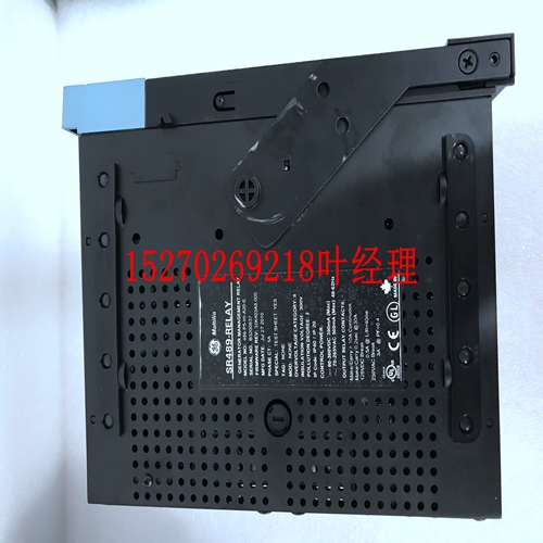
IS200IVFBG1A模块备件,模块控制器
3504E型高密度模块是一个例外,它没有通道间隔离。3502E、3503E和3505E型包括自检功能,用于验证Tricon控制器检测从正常通电电路到关闭状态的转换的能力。由于大多数安全系统使用断电跳闸设置,因此检测关闭状态的能力是一项重要功能。为了测试是否有卡滞的接通输入,闭合输入电路内的开关,以允许光学隔离电路读取零输入(关)。测试运行时,最后一次数据读取被冻结在I/O处理器中。单数字输入模块在单数字输入模件上,只有确保安全操作所需的信号路径部分是三倍的。单个模块针对低成本比最大可用性更重要的安全关键应用进行了优化。专用自检电路可在不到半秒的时间内检测非三重信号调节器内的所有卡在打开和关闭位置的故障情况。这是故障安全系统的强制性特征,该系统必须及时检测所有故障,并且在检测到输入故障时,强制将测量的输入值设置为安全状态。由于Tricon针对断电跳闸应用进行了优化,因此检测到输入电路中的故障会强制关闭(断电状态)每个通道向主处理器报告的值。数字输出模块每个数字输出模块都包含三个相同的隔离通道的电路。每个通道包括一个I/O微处理器,该微处理器从其相应主处理器上的I/O处理器接收其输出表。除双DC模块外,所有数字输出模块均使用获得专利的四倍输出电路,称为Quad Vorter,在将单个输出信号施加到负载之前对其进行表决。该表决器电路基于并联串联路径,如果通道A和B、通道B和C或通道A和C的驱动器命令它们关闭,即,3个驱动器中有2个被表决为“开”,则通过并联串联路径。双数字输出模块提供单串联路径,Tricon v9–v10系统3的2选1操作理论13规划和安装指南分别适用于每个交换机。四倍输出电路为所有关键信号路径提供多重冗余,确保安全性和最大可用性。有关规格,请参阅第87页的数字输出模块。OVD(输出表决器诊断)每个数字输出模块对每个点执行特定类型的输出表决器检测(OVD)。该安全功能允许在多种多种故障情况下不受限制地运行。一般来说,在OVD执行期间,每个点的命令状态在一个输出驱动器上立即反转,一个接一个。模块上的回路允许每个微处理器读取该点的输出值,以确定输出电路中是否存在潜在故障。(对于不能容忍任何长度的信号转换的设备,可以禁用交流和直流电压数字输出模块上的OVD。)交流数字输出模块在交流电压数字输出模件上,OVD过程识别的故障开关会导致输出信号转换到相反的状态,最多持续半个交流周期。这种转换可能对所有现场设备都不透明。检测到故障后,模块中断OVD的进一步迭代。交流电压数字输出模块上的每个点都需要周期性地循环至开和关状态,以确保100%的故障覆盖率。直流数字输出模块直流电压数字输出模块专门设计用于控制长时间将点保持在一个状态的设备。直流电压数字输出模块的OVD策略确保即使点的命令状态从未改变,也能完全覆盖故障。在这种类型的模块上,输出信号转换通常发生在OVD执行期间,但保证小于2.0毫秒(通常为500微秒),并且对大多数现场设备是透明的。双直流数字输出模块双数字输出(DDO)模块提供了足够的冗余,以确保安全运行。双模块针对低成本比最大可用性更重要的安全关键应用进行了优化。受监控的数字输出模块受监控的数据输出模块提供电压和电流环回,允许对通电跳闸和断电跳闸条件进行完全故障覆盖。此外,监控数字输出模块通过进行连续电路连续性检查来验证现场负载的存在。模块会通知任何现场负载损失。
The model 3504E high-density module is an exception—it has no channel-to-channel isolation. Models 3502E, 3503E, and 3505E include a self-test feature which verifies the ability of the Tricon controller to detect transitions from a normally energized circuit to the Off state. Because most safety systems use a de-energize-to-trip setting, the ability to detect the Off state is an important feature. To test for stuck-On inputs, a switch within the input circuitry is closed to allow a zero input (Off) to be read by the optical isolation circuitry. The last data reading is frozen in the I/O Processor while the test is running. Single Digital Input Modules On Single Digital Input Modules, only those portions of the signal path which are required to ensure safe operation are triplicated. Single modules are optimized for those safety-critical applications where low cost is more important than maximum availability. Special self-test circuitry detects all stuck-On and stuck-Off fault conditions within the non-triplicated signal conditioners in less than half a second. This is a mandatory feature of a fail-safe system, which must detect all faults in a timely manner and upon detection of an input fault, force the measured input value to the safe state. Because the Tricon is optimized for de-energize-to-trip applications, detection of a fault in the input circuitry forces to Off (the de-energized state) the value reported to the Main Processors by each channel. Digital Output Modules Every Digital Output Module houses the circuitry for three identical, isolated channels. Each channel includes an I/O microprocessor which receives its output table from the I/O Processor on its corresponding Main Processor. All of the Digital Output Modules, except the dual DC modules, use a patented quadruplicated output circuitry, referred to as Quad Voter, which votes on the individual output signals just before they are applied to the load. This voter circuitry is based on parallel-series paths which pass power if the drivers for Channels A and B, or Channels B and C, or Channels A and C command them to close—in other words, 2-out-of-3 drivers voted On. Dual Digital Output Modules provide a single series path, with the 2-out-of- Theory of Operation 13 Planning and Installation Guide for Tricon v9–v10 Systems 3 voting process applied individually to each switch. The quadruplicated output circuitry provides multiple redundancy for all critical signal paths, guaranteeing safety and maximum availability. For specifications, see Digital Output Modules on page 87. OVD (Output Voter Diagnostics) Every Digital Output Module executes a specific type of Output Voter Diagnostics (OVD) for every point. This safety feature allows unrestricted operation under a variety of multiple-fault scenarios. In general, during OVD execution the commanded state of each point is momentarily reversed on one of the output drivers, one after another. Loop-back on the module allows each microprocessor to read the output value for the point to determine whether a latent fault exists within the output circuit. (For devices that cannot tolerate a signal transition of any length, OVD on both AC and DC voltage Digital Output Modules can be disabled.) AC Digital Output Modules On AC voltage Digital Output Modules, a fault switch identified by the OVD process causes the output signal to transition to the opposite state for a maximum of half an AC cycle. This transition may not be transparent to all field devices. After a fault is detected, the module discontinues further iterations of OVD. Each point on an AC voltage Digital Output Module requires periodic cycling to both the On and Off states to ensure 100 percent fault coverage. DC Digital Output Modules DC voltage Digital Output Modules are specifically designed to control devices which hold points in one state for long periods of time. The OVD strategy for a DC voltage Digital Output Module ensures full fault coverage even if the commanded state of the points never changes. On this type of module, the output signal transition normally occurs during OVD execution, but is guaranteed to be less than 2.0 milliseconds (500 microseconds is typical) and is transparent to most field devices. Dual DC Digital Output Modules Dual Digital Output (DDO) Modules provides just enough redundancy to ensure safe operation. Dual modules are optimized for those safety-critical applications where low cost is more important than maximum availability. Supervised Digital Output Modules Supervised Digital Output Modules provide both voltage and current loopback, allowing complete fault coverage for both energized-to-trip and de-energized-to-trip conditions. In addition, a Supervised Digital Output Module verifies the presence of the field load by doing continuous circuit-continuity checks. Any loss of field load is annunciated by the module.


