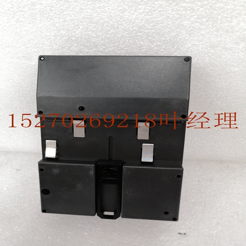
IS200JPDMG1A自动化模块备件
断开式和保险丝式插入端子,每行一组模块的接线。当相关的VersaMax模块提供16点组的连接时,该接线格式通常适用。此类模块的一个例子是VersaMax 24 V DC 16pt输出模块。当以这种格式连接插入式断路器或熔断器底座时,请遵循以下指南:将现场设备连接至A1-A16(或B1-B16,如适用)将现场设备的回流线连接至相应的公共连接–A1至W1、A2至W2、A9至X1、A10至X2等。连接A17、W和X端子(或B17、Y和Z)之间的跳线连接A17和A18(或B18和B18)之间的电源GFK-1504N第2章安装2-31 2示例:输出模块IC200MDL740的布线下图提供了与VersaMax模块一起使用时IC200CHS101或121的现场布线示例,每个端子排有一组。J1 J2 Q1 J1 J2 IC200CHS101 IC200CHS121断开式或保险丝式插入端子,每行两组模块的接线当相关的VersaMax模块提供8点组连接时,该接线格式通常适用。此类模块的一个示例是VersaMax 24 V DC 16pt输入模块IC200MDL640。1 2 3 4 5 6 7 8 9 10 11 12 13 14 15 16 17 18 I1 I2 I3 I4 I5 I6 I7 I8 I9 I10 11 I12 I13 I14 I15 I16 A+-(-)(+)+-(-)-(+)-((+))当以这种格式连接插入式断路器或保险丝底座时,请遵循以下指南:将现场设备连接到A1-A16(或B1-B16,如果适用)将现场设备的回流线连接到相应的公共连接–A1到W1,A2到W2,A9至X1、A10至X2等。连接A17和W(或B17和Y)之间的电源。连接A18和X(或B18和Z)之间的电源。2-32 VersaMax模块、电源和托架用户手册GFK-1504N 2模块IC200MDL640的接线图示例下图提供了与VersaMax组件一起使用时IC200CHS101或121的现场接线示例,每个端子排有2组。J1 J2 I1 J1J2 I1 IC200CHS101 IC200CHS121断开式或保险丝式插入端子,带有未分组连接的模块的接线。当相关VersaMax模块提供隔离设备的连接时,该接线格式通常适用,但当非隔离模块为每个公共连接提供专用端子时,也可以使用该接线格式。隔离模块的示例是VersaMax 120V AC 8pt隔离输入模块,
Disconnect-Style and Fuse-Style Interposing Terminals, Wiring for Modules with One Group per Row This wiring format generally applies when the associated VersaMax module provides for connection of in 16-point groups. An example of such a module is the VersaMax 24 V DC 16pt Output Module, When connecting an Interposing Disconnect or Fuse base in this format, follow these guidelines: Connect the field devices to A1-A16 (or B1-B16 where appropriate) Connect the return wires of field devices to the corresponding common connections – A1 to W1, A2 to W2, A9 to X1, A10 to X2, and such. Connect jumpers between the A17, W, and X terminals (or B17, Y, and Z) Connect the power supply between A17 and A18 (or B17 and B18) GFK-1504N Chapter 2 Installation 2-31 2 Example: Wiring for Output Module IC200MDL740 The following figures provide example field wiring for IC200CHS101 or 121 when used with VersaMax modules with 1 group per terminal row. J1 J2 Q1 Q1 J1 J2 IC200CHS101 IC200CHS121 Disconnect-Style or Fuse-Style Interposing Terminals, Wiring for Modules with Two Groups per Row This wiring format generally applies when the associated VersaMax module provides for connection of in 8-point groups. An example of such a module is the VersaMax 24 V DC 16pt Input Module, IC200MDL640. 1 2 3 4 5 6 7 8 9 10 11 12 13 14 15 16 17 18 I1 I2 I3 I4 I5 I6 I7 I8 I9 I10 11 I12 I13 I14 I15 I16 A + - (-) (+) + - (-) (+) - (+) - (+) When connecting the Interposing Disconnect or Fuse bases in this format, follow these guidelines: Connect field devices to A1-A16 (or B1-B16 where appropriate) Connect return wires of field devices to the corresponding common connections – A1 to W1, A2 to W2, A9 to X1, A10 to X2, and such. Connect power supply between A17 and W (or B17 and Y). Connect power supply between A18 and X (or B18 and Z). 2-32 VersaMax Modules, Power Supplies and CarriersUser Manual GFK-1504N 2 Example Wiring Diagram for Module IC200MDL640 The following figures provide example field wiring for IC200CHS101 or 121 when used with VersaMax modules with 2 groups per terminal row. J1 J2 I1 J1 J2 I1 IC200CHS101 IC200CHS121 Disconnect-Style or Fuse-Style Interposing Terminals, Wiring for Modules with Connections that are Not Grouped This wiring format generally applies when the associated VersaMax module provides for connection of isolated devices, but may also be used when a non-isolated module provides dedicated terminals for each common connection. An example of an isolated module is the VersaMax 120V AC 8pt Isolated Input Module,


